High-power direct-current charging system

A DC charging, high-power technology, applied in the direction of converting DC power input to DC power output, charging stations, and converting irreversible AC power input to DC power output, etc., can solve the problem of reducing the complexity of the charging system and the volume of the charging system , cost and operation and maintenance, reducing the number of charging pile modules stacking and other issues, to achieve the effect of improving maintenance difficulty, reducing volume and cost, and reducing complexity

Pending Publication Date: 2021-01-01
SHANGHAI ZHONGLIAN NENGCHUANG NEW ENERGY TECH CO LTD
View PDF1 Cites 0 Cited by
  • Summary
  • Abstract
  • Description
  • Claims
  • Application Information

AI Technical Summary

Problems solved by technology

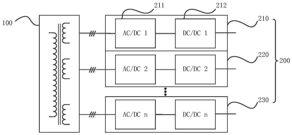
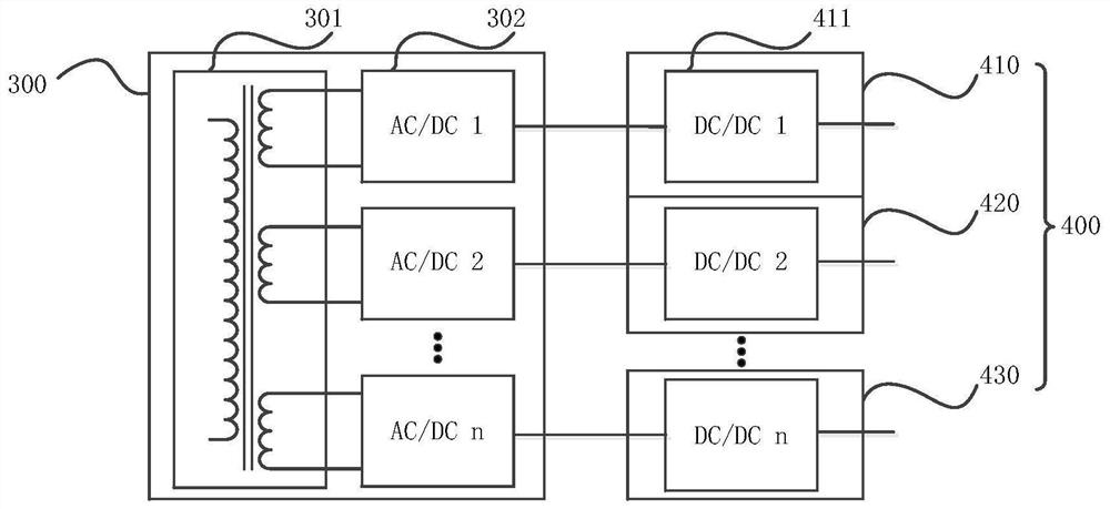
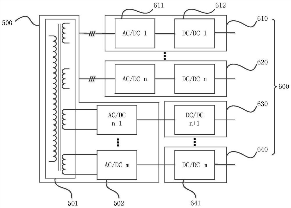
[0006] The technical problem to be solved by the present invention is to provide a high-power DC charging system to solve the problems of complexity, volume, cost and operation and maintenance of the charging system brought about by the current power distribution solution. Problem, without switching the output switch and connecting different modules in parallel or bypassing, it can realize the function of fast charging the power receiving terminal with different requirements, reduce the stacking number of charging pile modules, reduce or even eliminate the existing charging The power switching unit of the system reduces the complexity of the charging system, reduces the volume and cost of the charging pile, and improves the maintenance difficulty of the charging pile

Method used


Image

  • High-power direct-current charging system
  • High-power direct-current charging system
  • High-power direct-current charging system

Examples


Embodiment Construction

[0018] The specific embodiments of the present invention will be further described below in conjunction with the accompanying drawings. It should be noted here that the descriptions of these embodiments are used to help understand the present invention, but are not intended to limit the present invention. In addition, the technical features involved in the various embodiments of the present invention described below may be combined with each other as long as they do not constitute a conflict with each other.

[0019] In describing the present invention, it should be understood that the terms "center", "longitudinal", "transverse", "length", "width", "thickness", "upper", "lower", "front", " Back", "Left", "Right", "Vertical", "Horizontal", "Top", "Bottom", "Inner", "Outer", "Clockwise", "Counterclockwise", "Axial", The orientation or positional relationship indicated by "radial", "circumferential", etc. is based on the orientation or positional relationship shown in the drawi...


PUM


Abstract

The invention relates to the technical field of charging systems, and particularly discloses a high-power direct-current charging system which comprises a multi-secondary-side winding transformer anda plurality of charging devices, the secondary side of the multi-secondary-side winding transformer is connected with a plurality of AC / DC converters, one end of each AC / DC converter is electrically connected with the secondary side of the multi-secondary-side winding transformer, and the other end of the AC / DC converter is connected with a plurality of DC / DC converters, and the DC / DC converters are arranged in the charging equipment. According to the invention, the function of quickly charging the power receiving terminals with different requirements can be realized without switching an output switch and connecting different modules in parallel or bypassing, the stacking number of the charging pile modules is reduced, a power switching unit of the existing charging system is reduced or even removed, the complexity of the charging system is reduced, and the charging efficiency is improved. The size and the cost of the charging pile are reduced, and the maintenance difficulty of the charging pile is improved.

Description

technical field [0001] The invention relates to the technical field of charging systems, in particular to a high-power DC charging system. Background technique [0002] Facing the increasingly urgent energy crisis, the development of electric vehicles has become an important development strategy of the country. In the development of electric vehicles, the construction of charging facilities is extremely important, and the number and charging speed of charging facilities restrict the development of electric vehicles. [0003] With the continuous improvement of battery capacity and technology, the charging current is getting bigger and bigger, the charging power demand is also getting bigger and bigger, and the output range is getting wider and wider. This puts forward higher requirements for charging facilities: multi-charging in one machine, automatic power distribution, flexible charging, etc., especially limited by the power of a single charging module, so that in order t...

Claims


Application Information

Patent Timeline
Patent Type & Authority Applications(China)
IPC IPC(8): B60L53/60B60L53/31H02M7/02H02M3/00
CPCB60L53/31B60L53/60H02M3/00H02M7/02H02J2207/20Y02T10/70Y02T10/7072Y02T10/72Y02T90/12
Inventor 李岩
Owner SHANGHAI ZHONGLIAN NENGCHUANG NEW ENERGY TECH CO LTD
Why Eureka
Try Eureka