Household garbage pyrolysis energy storage controllable pyrolysis bin

A technology for domestic waste and energy storage, applied in lighting and heating equipment, combustion methods, combustion types, etc., can solve the problem that the pyrolysis treatment technology is difficult to achieve large-scale, restricts waste pyrolysis treatment devices, and is difficult to achieve high temperature environments, etc. problems, to achieve the effect of eliminating dioxin hazards, reducing costs, maintaining continuity and stability

Pending Publication Date: 2021-01-01
广州华富能环保科技有限公司
View PDF0 Cites 0 Cited by
  • Summary
  • Abstract
  • Description
  • Claims
  • Application Information

AI Technical Summary

Problems solved by technology

However, although the pyrolysis treatment technology is good, there are several technical bottlenecks that limit the development of waste pyrolysis treatment devices: First, waste pyrolysis is best carried out in an anaerobic environment, but it is difficult to carry out in the same equipment It can be done; the second is that waste pyrolysis is best carried out in a relatively high temperature environment. Since the original calorific value of waste is relatively low, it is difficult to achieve a high temperature environment by adopting self-consumption heating under the condition of cost control; The third is that pyrolysis treatment technology is difficult to achieve large-scale so far, so it also limits the application of this technology

Method used


Image

  • Household garbage pyrolysis energy storage controllable pyrolysis bin
  • Household garbage pyrolysis energy storage controllable pyrolysis bin
  • Household garbage pyrolysis energy storage controllable pyrolysis bin

Examples


Embodiment Construction

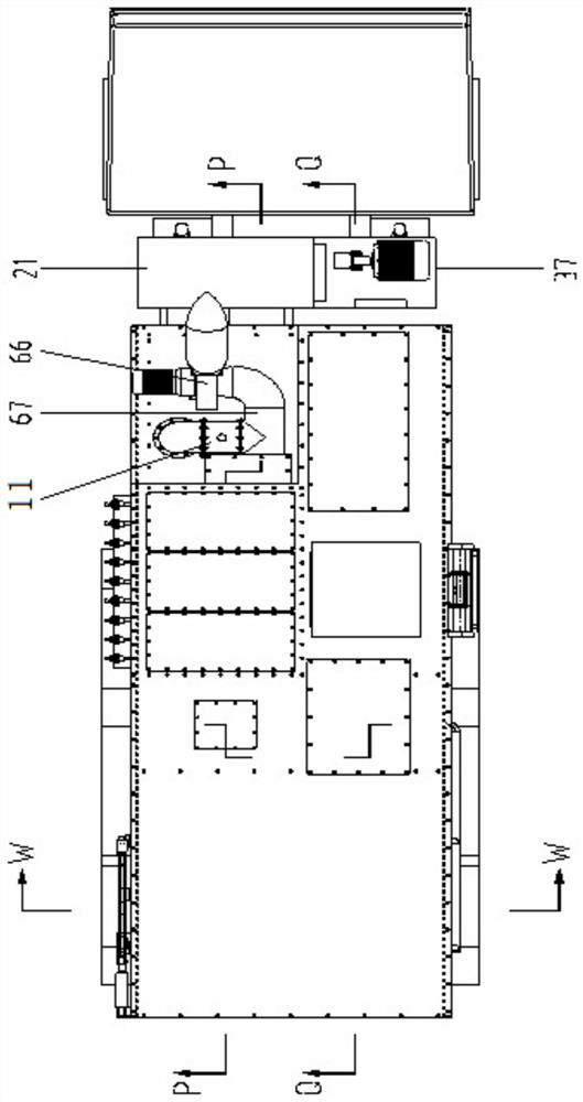
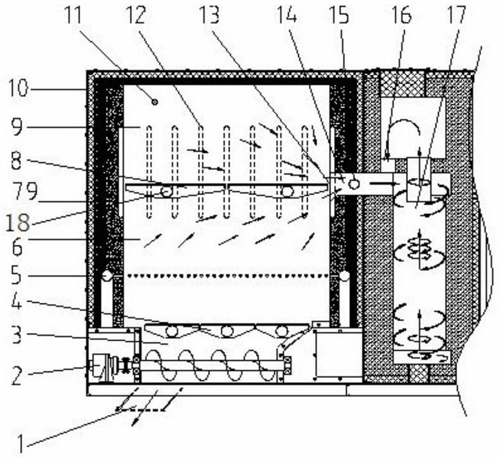
[0022] The domestic garbage pyrolysis energy storage controllable pyrolysis bin of the present invention is as follows: Figure 1-3 As shown, include pyrolysis bin 9 and incineration bin 6, energy storage wall 79, heat pipe row 12 and high temperature resistant energy storage turnover plate 8, and supporting hydraulic overturning mechanism. The first combustion chamber energy storage controllable pyrolysis chamber 9 and incineration chamber 6 are the main chambers for the pyrolysis treatment of domestic waste in the mobile domestic waste pyrolysis treatment station, wherein the energy storage controllable pyrolysis chamber 9 is located in the first combustion chamber The upper layer, the incineration bin 6 is located in the middle layer of the first combustion chamber, and below the energy storage controllable pyrolysis bin 9.

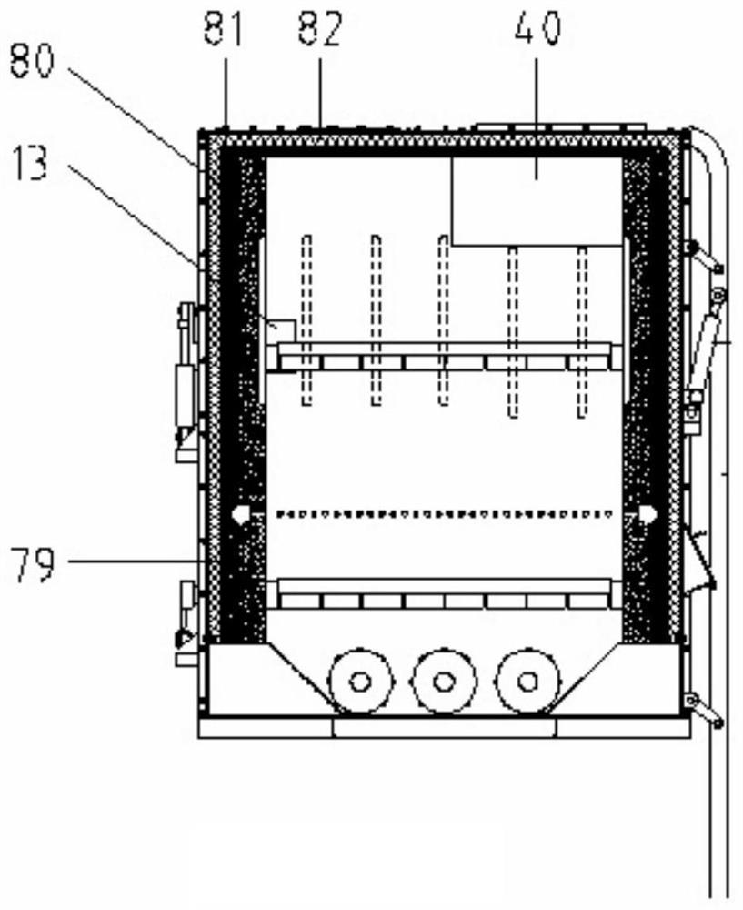
[0023] The energy storage controllable pyrolysis bin 9 is a hexahedral square structure, the surrounding and top floors are energy storage walls 79, a...


PUM


Abstract

The invention provides a household garbage pyrolysis energy storage controllable pyrolysis bin. Energy storage wall bodies are arranged on the periphery and the top layer of a first combustion chamber, energy storage turning plates are installed in the first combustion chamber, the space, located above the energy storage turning plates, in the first combustion chamber is a pyrolysis bin, the space, located below the energy storage turning plates, in the first combustion chamber is an incineration bin, a feeding port is formed in the upper portion of the first combustion chamber, and a common gas outlet is formed in the junction of the incineration bin and the pyrolysis bin on the first combustion chamber; and the two energy storage turning plates are installed on two symmetrically-installed rotating shafts respectively, the two ends of the two rotating shafts are installed on the energy storage wall bodies respectively, and the rotating shafts are connected with a turning plate oil cylinder. According to the household garbage pyrolysis energy storage controllable pyrolysis bin, a closed anaerobic environment can be constructed, meanwhile, the temperature of garbage is rapidly increased to the medium-high temperature of 500-700 DEG C through energy storage and energy release, and environmental pollution is reduced.

Description

technical field [0001] The invention relates to the technical field of domestic waste treatment. Background technique [0002] Domestic waste disposal is a worldwide problem. At present, domestic waste disposal mainly adopts technologies such as landfill, composting and incineration. According to the analysis, both landfill and composting must occupy a large amount of land resources and cause environmental pollution, which is no longer suitable for promotion at present, while waste incineration will produce a large amount of toxic and harmful substances, especially dioxins. In contrast, the pyrolysis treatment of garbage can not only inhibit the formation of dioxins, but also produce a very small amount of smoke, which will no longer cause harm after a little purification treatment. Therefore, pyrolysis treatment of garbage is by far the most effective way to treat garbage. good technique. However, although the pyrolysis treatment technology is good, there are several tech...

Claims


Application Information

Patent Timeline
Patent Type & Authority Applications(China)
IPC IPC(8): F23G5/027F23G5/16F23G5/44F23G5/46
CPCF23G5/0276F23G5/16F23G5/44F23G5/46F23G2201/304F23G2202/103F23G2206/10
Inventor 黄超隆武强陈雷连波樊大龙霍有荔陈建帆张守荣
Owner 广州华富能环保科技有限公司
Why Eureka
Try Eureka