Gas stove and gas stove control method

A control method and technology for gas stoves, which are applied in the field of household kitchen utensils, can solve problems such as the inability to automatically adjust the damper structure of gas stoves, and achieve the effects of stabilizing combustion conditions, reducing emissions, and saving human resources.

Pending Publication Date: 2021-01-01
GREE ELECTRIC APPLIANCES INC
View PDF0 Cites 1 Cited by
  • Summary
  • Abstract
  • Description
  • Claims
  • Application Information

AI Technical Summary

Problems solved by technology

[0004] Therefore, the technical problem to be solved by the present invention is to overcome the defect that the damper structure of the gas stove in the prior art cannot be automatically adjusted, thereby providing a gas stove and a gas stove control method

Method used


Image

  • Gas stove and gas stove control method
  • Gas stove and gas stove control method
  • Gas stove and gas stove control method

Examples


Embodiment 1

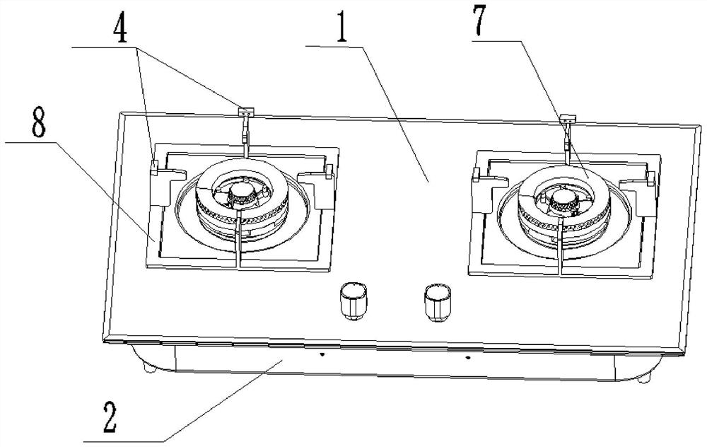
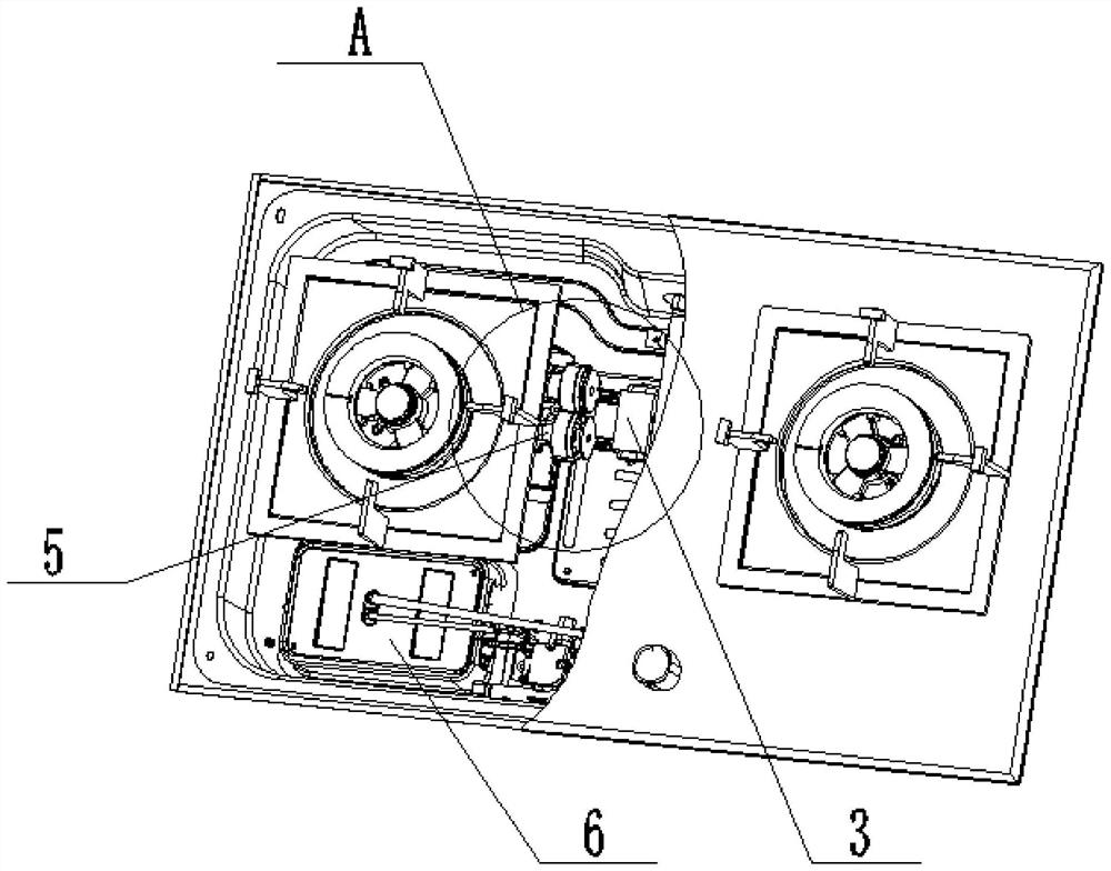
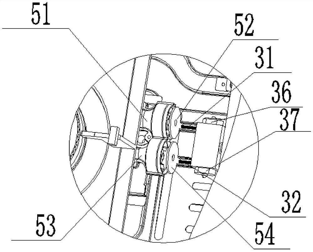
[0055] like figure 1 - Figure 5 , the present embodiment provides a gas stove, including a panel 1 and a bottom case 2, the panel 1 is provided with two burners 7 and a switch knob, and a support structure 8 for carrying pots is arranged along the circumference of the burner 7, The bottom shell 2 is also provided with a damper structure 5, the damper structure 5 includes an ejector tube, one end of the ejector tube is connected to the burner 7, and the other end is provided with a flange annular port, and the port is provided with a damper sheet structure correspondingly. In addition, the gas stove also includes: a damper adjustment device 3 , a gas detection device 4 and a controller 6 .

[0056] The damper adjusting device 3 is arranged adjacent to the burner 7 inside the bottom casing 2, and is movably connected with the damper structure 5, and can adjust the ventilation volume of the damper structure 5;

[0057] The gas detection device 4 is arranged on the panel 1, and...

Embodiment 2

[0074] This embodiment provides a gas stove control method, such as Image 6 As shown, the gas stove includes a damper structure 5 and an ejector tube structure, including the following steps:

[0075] S1. Obtain the volume fraction of carbon monoxide;

[0076] In this embodiment, the volume fraction of carbon monoxide indicates the ratio between the volume Vco of carbon monoxide entering the inside of the gas stove and the total gas Vgas entering the inside of the gas stove. Vgas includes not only the volume of carbon monoxide, but also oxygen, nitrogen and air. other trace gases, etc. Specifically, the volume fraction of carbon monoxide is defined as: Vco / Vgas.

[0077] S2. Determine whether the volume fraction of carbon monoxide falls within the preset range;

[0078] In this embodiment, the set interval value is [0.02-0.03].

[0079] S3. Control the damper structure 5 to approach or move away from the ejection tube structure according to whether it falls within a prese...


PUM


Abstract

The invention provides a gas stove and a gas stove control method. The gas stove comprises a panel and a bottom shell, wherein the panel is provided with a combustor and a support structure arranged in the circumferential direction of the combustor. The gas stove further comprises an air door adjusting device, a gas detection device and a controller, wherein the air door adjusting device is arranged inside the bottom shell and is suitable for adjusting the ventilation amount of an air door structure connected with the combustor; the gas detection device is arranged on the panel and is suitablefor detecting gas components in smoke emitted by the combustor in a working state; and the controller is arranged inside the bottom shell and is in communication connection with the air door adjusting device and the gas detection device. The gas components in the smoke are detected through the gas detection device, after signals are transmitted to the controller, whether the air supply amount ofthe combustor in the working environment is sufficient or not is judged through comparison and recognition, the ventilation amount of the air door adjusting device is controlled according to the condition, normal work of the combustor is guaranteed, the air door structure can be automatically adjusted, the combustion working condition is more stable and efficient, and a user can use the gas stoveconveniently.

Description

technical field [0001] The invention relates to the technical field of household kitchenware, in particular to a gas stove and a gas stove control method. Background technique [0002] With the rapid development of society, residents have higher and higher requirements for the quality of life, but the intelligence of common gas stoves is still relatively low, and professional personnel are required to install and adjust the damper at the door, so that the combustion conditions are fixed and the operating environment If the user accidentally touches the damper, the combustion conditions will be changed, and various problems will occur. At this time, professionals need to come to adjust the door, which consumes manpower and material resources. [0003] In the prior art, the air door cover is driven by a motor to move relative to the air inlet to change the opening of the air inlet, and the motor is controlled by the controller to realize the electric function of air door adjus...

Claims


Application Information

Patent Timeline
Patent Type & Authority Applications(China)
IPC IPC(8): F24C3/12
CPCF24C3/126
Inventor 王运发刘梦茹佘帅征周文通段聪聪刘书兴
Owner GREE ELECTRIC APPLIANCES INC
Why Eureka
Try Eureka