High-sensitivity temperature detection device based on cantilever beam

A detection device and a cantilever beam technology are applied in the field of temperature detection, which can solve the problems of low detection sensitivity and achieve the effects of high temperature detection sensitivity and good application prospects.

Inactive Publication Date: 2021-01-01
金华伏安光电科技有限公司
View PDF0 Cites 1 Cited by
  • Summary
  • Abstract
  • Description
  • Claims
  • Application Information

AI Technical Summary

Problems solved by technology

Traditional temperature detectors are based on thermal resistance or thermocouples with low detection sensitivity

Method used


Image

  • High-sensitivity temperature detection device based on cantilever beam
  • High-sensitivity temperature detection device based on cantilever beam
  • High-sensitivity temperature detection device based on cantilever beam

Examples


Embodiment 1

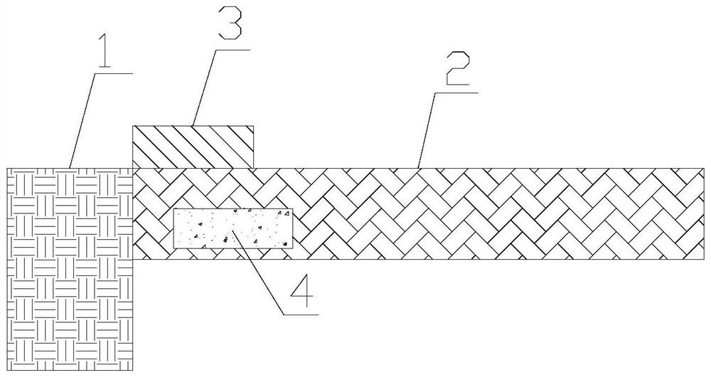
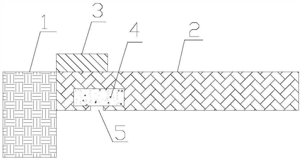
[0021] The invention provides a high-sensitivity temperature detection device based on a cantilever beam. like figure 1 As shown, the high-sensitivity temperature detection device based on a cantilever beam includes a vibration source 1 , a cantilever beam 2 , a piezoelectric material block 3 , and a thermal expansion material part 5 . The cantilever beam 2 is fixed on the vibration source 1 . The vibration source 1 drives the cantilever beam 2 to vibrate. The material of the cantilever beam 2 is aluminum alloy, silicon, semiconductor material, diamond. The piezoelectric material block 3 is arranged on the top surface of the cantilever beam 2 near the fixed end, and the piezoelectric material block 3 is connected with an external circuit for detecting the vibration frequency of the cantilever beam 2 . The piezoelectric material block 3 is made of piezoelectric ceramics or polyvinylidene fluoride. The thermally expandable material portion 4 is provided inside the cantilever...

Embodiment 2

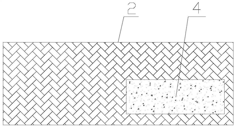
[0024] On the basis of Embodiment 1, the heat-expandable material part 4 is disposed in a position near the fixed end of the cantilever beam 2 . Under the action of the vibration source 1, when the cantilever beam 2 vibrates, a large degree of bending occurs near the fixed end of the cantilever beam 2. When the heat-expandable material part 4 is arranged in the position near the fixed end of the cantilever beam 2, the effect of the expansion of the heat-expandable material part 4 on the change of the internal stress of the cantilever beam 2 is more obvious, thereby changing the resonant frequency of the cantilever beam 2 more, thereby realizing a more stable High sensitivity magnetic field detection.

Embodiment 3

[0026] On the basis of Embodiment 2, the section of the cantilever beam 2 is rectangular. The section of the thermally expandable material part 4 is rectangular. The cross-section of the heat-expandable material part 4 is asymmetrically arranged within the cross-section of the cantilever beam 2 . In this way, the expansion of the thermal expansion material part 4 not only changes the stress in the cantilever beam 2, but also changes the stress of the cantilever beam 2 in different directions in the section of the cantilever beam 2, thus causing the cantilever beam 2 to twist. The resonant frequency of the cantilever beam 2 can be changed more precisely, so as to realize higher sensitivity magnetic field detection.


PUM


Abstract

The invention provides a high-sensitivity temperature detection device based on a cantilever beam. The high-sensitivity temperature detection device comprises a vibration source, the cantilever beam,a piezoelectric material block and a thermal expansion material part. The cantilever beam is fixed on the vibration source, the piezoelectric material block is arranged on a position, close to a fixedend, of a top surface of the cantilever beam, the piezoelectric material block is connected with an external circuit, and the thermal expansion material part is arranged in the cantilever beam. During application, in a to-be-measured environment, the thermal expansion material part absorbs heat and expands so that the stress and distribution of the cantilever beam are changed, a resonant frequency of the cantilever beam is changed, and the to-be-measured temperature is measured by detecting the change of the resonant frequency of the cantilever beam. The device has the advantage of high temperature detection sensitivity, and has a good application prospect in the field of high-sensitivity temperature detection.

Description

technical field [0001] The invention relates to the field of temperature detection, in particular to a high-sensitivity temperature detection device based on a cantilever beam. Background technique [0002] Temperature measurement involves many fields of engineering technology. A temperature detector is a device that can sense temperature and convert it into an output signal. Traditional temperature detectors are based on thermal resistance or thermocouples, which have low detection sensitivity. Contents of the invention [0003] In order to solve the above problems, the present invention provides a high-sensitivity temperature detection device based on a cantilever beam, comprising: a vibration source, a cantilever beam, a piezoelectric material block, and a thermal expansion material part; the cantilever beam is fixed on the vibration source, and the piezoelectric material block It is arranged on the top surface of the cantilever beam close to the fixed end, the piezoe...

Claims


Application Information

Patent Timeline
Patent Type & Authority Applications(China)
IPC IPC(8): G01K11/26
CPCG01K11/26
Inventor 不公告发明人
Owner 金华伏安光电科技有限公司
Why Eureka
Try Eureka