Pest killing device for plant protection

A technology for plant protection and deinsectization, which is applied to the device for catching or killing insects, application, animal husbandry, etc. It can solve the problems of insufficient attractiveness of pests and low efficiency of desinsection, so as to improve the attractiveness and practicability , Improve the efficiency of pest control

Inactive Publication Date: 2021-01-05
张莉
View PDF0 Cites 1 Cited by
  • Summary
  • Abstract
  • Description
  • Claims
  • Application Information

AI Technical Summary

Problems solved by technology

[0003] Existing insect extermination devices for plant protection generally use insect trap lamps to lure pests, but insect trap lamps are generally fixed, and the attraction to pests is not enough, resulting in low efficiency of insect extermination

Method used


Image

  • Pest killing device for plant protection
  • Pest killing device for plant protection
  • Pest killing device for plant protection

Examples


Embodiment 1

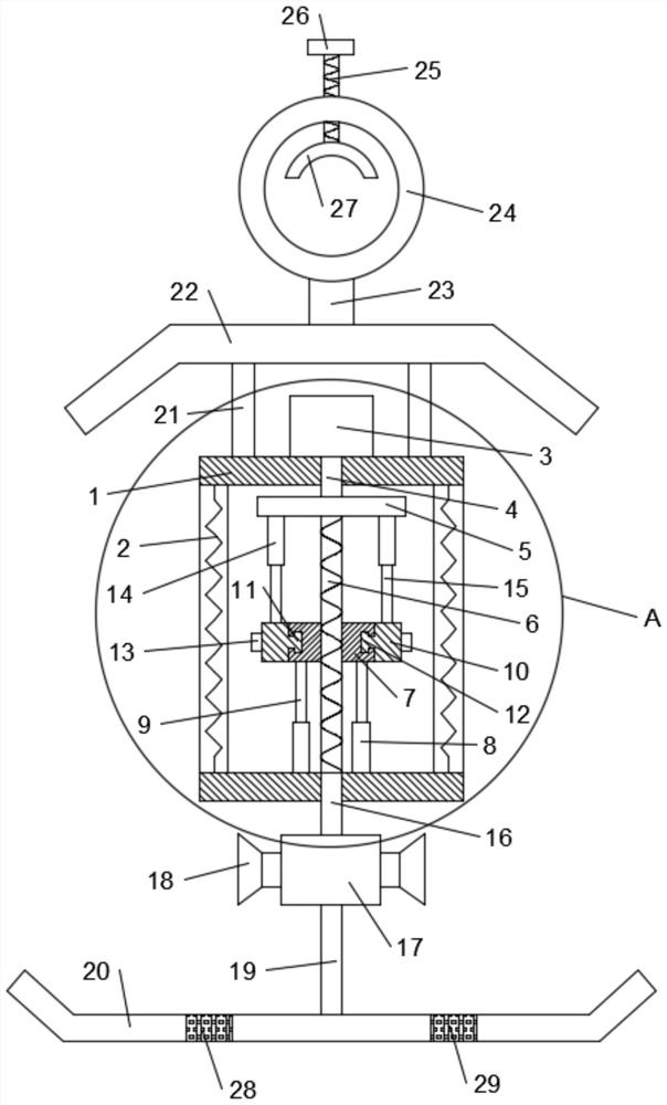
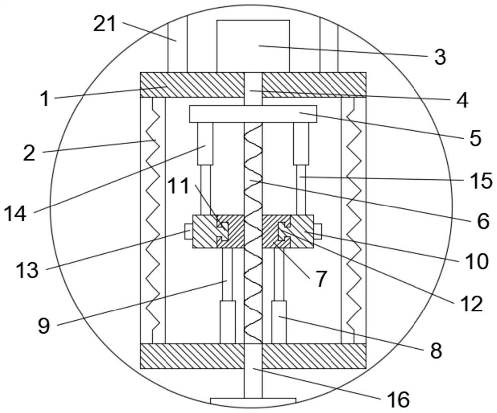
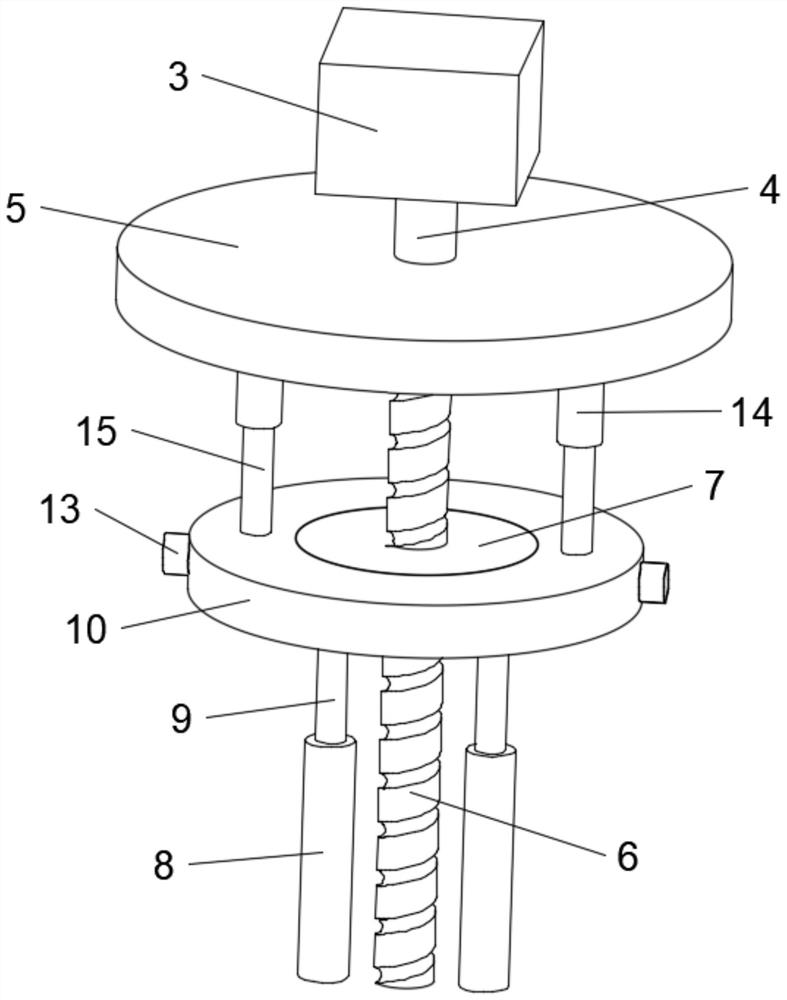
[0020] see Figure 1-3 , in an embodiment of the present invention, a pest control device for plant protection includes a lampshade 1, a power grid 2 is arranged on the side walls around the lampshade 1, a motor 3 is arranged on the upper end of the lampshade 1, and the output end of the motor 3 is fixedly connected with a The shaft 4 extends into the lampshade 1 and the end of the shaft 4 is fixedly connected with a flat plate 5, the lower end of the flat plate 5 is fixedly connected with a screw 6, the screw 6 is slidably mounted with a slider 7, and the lower end of the slider 7 is provided with a movable rod 9, The inner bottom surface of the lampshade 1 is provided with a sleeve-8, and the movable rod-9 is slidably installed in the sleeve-8. The slider 7 is provided with a rotating device, which is connected with an insect trap lamp 13, and the motor 3 is started. The shaft rod 4 drives the flat plate 5 to rotate, and then the screw rod 6 rotates, and the slide block 7 sl...

Embodiment 2

[0028] In order to prevent rainwater from accumulating on the receiving tray 20, this embodiment is further improved on the basis of Embodiment 1. The improvements are: the receiving tray 20 is provided with a through hole 28, and the through hole 28 is provided with a screen 29. Through hole 28 is set, and when rain falls on receiving dish 20, can flow out by through hole 28, and screen cloth 29 can block pest, prevents it from leaking from receiving dish 20.

[0029] The working principle of this embodiment is: in order to prevent rainwater from accumulating on the receiving tray 20, a through hole 28 is provided on the receiving tray 20, and a screen 29 is arranged on the through hole 28. By setting the through hole 28, when the rainwater falls On the receiving tray 20, it can flow out through the through hole 28, and the screen cloth 29 can block the pests and prevent them from leaking out from the receiving tray 20.

[0030]To sum up, by installing the motor 3, the shaft ...


PUM


Abstract

The invention discloses a pest killing device for plant protection. The pest killing device comprises a lampshade, wherein a power grid is arranged on the peripheral side wall of the lampshade, and amotor is arranged at the upper end of the lampshade; the output end of the motor is fixedly connected with a shaft rod, the shaft rod extends into the lampshade, and the tail end of the shaft rod is fixedly connected with a flat plate; the lower end of the flat plate is fixedly connected with a screw rod, a sliding block is arranged on the screw rod in a sliding mode, and movable rods I are arranged at the lower end of the sliding block; sleeves I are arranged on the bottom face inside the lampshade, and the movable rods I are arranged in the sleeves I in a sliding mode; and rotating devices are arranged on the sliding block, and the rotating devices are connected with trap lamps. By arranging the motor, the shaft rod drives the flat plate to rotate, then the screw rod rotates, and the sliding block slides up and down; the trap lamps rotate through the rotating devices, so that the trap lamps rotate and move up and down at the same time, the attractive force of the trap lamps to pestscan be improved, and more pests are attracted; and the pests are killed through the power grid, so that the pest killing efficiency of the device is improved.

Description

technical field [0001] The invention relates to the field of plant protection devices, in particular to an extermination device for plant protection. Background technique [0002] Plant protection is also called plant medicine. It mainly needs to master the basic theories and basic knowledge of agricultural biological science, agricultural ecological science, agricultural pest weed biology and its damage, and receive basic training in the identification and identification of various pest weeds. , have the basic ability of monitoring and control of plant diseases, pests and weeds, and mainly study plant growth and environment, plant cultivation technology, plant pathology, agricultural insects, plant chemical protection, plant quarantine, enterprise management, basic skills training of plant protection, plant Cultivation technical skills training and plant genetic breeding technical skills training, etc. [0003] Existing insect extermination devices for plant protection gen...

Claims


Application Information

Patent Timeline
Patent Type & Authority Applications(China)
IPC IPC(8): A01M1/04A01M1/22A01M1/20A01M7/00
CPCA01M1/04A01M1/20A01M1/223A01M7/0003A01M7/005
Inventor 张莉
Owner 张莉
Why Eureka
Try Eureka