Biological filtration equipment for centralized treatment of waste gas of wastewater station

A centralized treatment and biological filtration technology, which is applied in the direction of dispersed particle filtration, dispersed particle separation, chemical instruments and methods, etc., can solve the problems such as the decline of the filtration effect of the filter layer, and achieve the effect of accelerating the air-drying speed

Inactive Publication Date: 2021-01-05
任丘市信中会计服务有限公司
View PDF0 Cites 8 Cited by
  • Summary
  • Abstract
  • Description
  • Claims
  • Application Information

AI Technical Summary

Problems solved by technology

[0003] If the waste water station is installed outdoors, and the outdoor temperature is high in summer, the moisture inside the waste water station will be heated and evaporated, so the evaporated water vapor will be inhaled by the waste gas centralized processor of the waste water station, and it will accumulate for a long time. A large amount of moisture adheres to the outside of the filter layer, which leads to a significant decrease in the filtering effect of the filter layer on the gas

Method used


Image

  • Biological filtration equipment for centralized treatment of waste gas of wastewater station
  • Biological filtration equipment for centralized treatment of waste gas of wastewater station
  • Biological filtration equipment for centralized treatment of waste gas of wastewater station

Examples


Embodiment 1

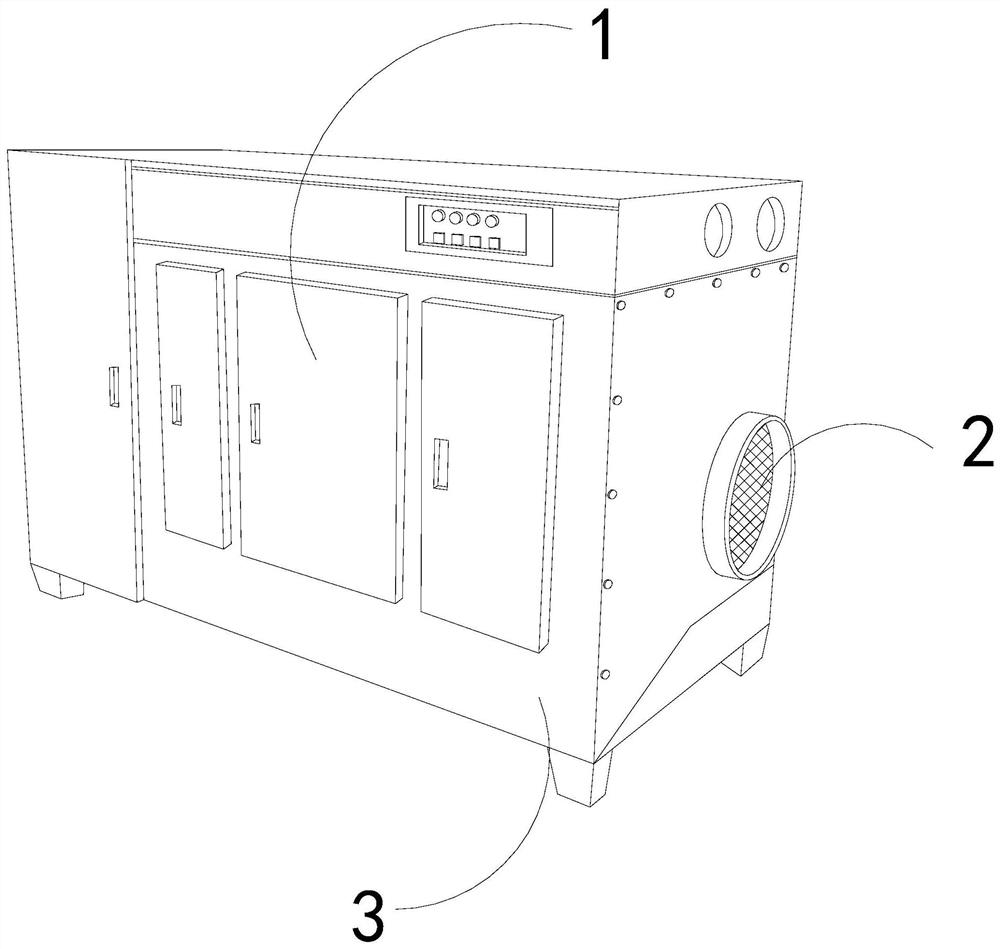
[0026] For example figure 1 -example Figure 5 Shown:

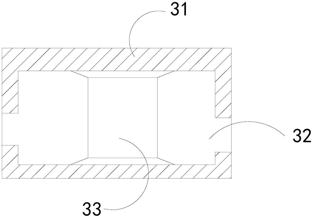
[0027] The invention provides a kind of biological filtration equipment for centralized treatment of waste gas in a waste water station. Its structure includes a sealed door 1, an air inlet 2, and a body 3. The mouth 2 is an integrated structure; the body 3 includes an outer frame 31, an inner cavity 32, and a filter layer 33. The inner cavity 32 and the outer frame 31 are an integrated structure, and the filter layer 33 is embedded in the outer frame 31. internal location.

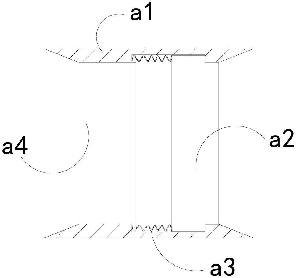
[0028] Wherein, the filter layer 33 includes a guide plate a1, a force plate a2, an elastic strip a3, and a fixed plate a4, the force plate a2 is movably engaged with the guide plate a1, and the elastic strip a3 is installed on the force plate a2 and fixed Between the plates a4, the exhaust gas generates an inward thrust on the force plate a2, which can make the force plate a2 slide inward along the guide plate a1 and shrink, and the force plate t...

Embodiment 2

[0034] For example Figure 6 -example Figure 8 Shown:

[0035] Wherein, the fixed plate a4 includes a blocking block c1, a swinging plate c2, an air collecting chamber c3, and an connecting plate c4. The blocking block c1 is embedded in the right side of the air collecting chamber c3. The inner part of the chamber c3 is movable and engaged, the gas-collecting chamber c3 and the connecting plate c4 are an integrated structure, and the swinging plate c2 is provided with three, which are evenly distributed in parallel inside the connecting plate c4, and the connecting plate is hit by a mechanism The vibration generated by c4 can make the oscillating plate c2 swing along the connecting plate c4, thereby generating an airflow to accelerate the drying speed of the moisture inside the connecting plate c4.

[0036] Wherein, the blocking block c1 includes an outer sliding plate c11, a connecting piece c12, and a transition block c13. The connecting piece c12 is installed between two...


PUM


Abstract

The invention discloses biological filtration equipment for centralized treatment of waste gas of wastewater station, which structurally comprises a sealing door, a gas inlet and a machine body, wherein the sealing door is connected with the front end of the machine body through a hinge, and the machine body and the gas inlet are of an integrated structure; According to the structure, when the gasinlet stops introducing waste gas, the stress plate can be pushed outwards quickly through the elastic strip to slide outwards along the guide plate, and then the impact ball can repeatedly impact the inner side of the contact plate under the cooperation of the elastic frame through inertia force generated by outward sliding of the stress plate; therefore, the outer swing plate can swing along the bearing plate, so that the outer swing plate can outwards bounce off moisture attached to the surface of the outer swing plate. Based on the compression of waste gas to the outer sliding plate, theouter sliding plate can slide and contract towards the middle part along the transition block, so that part of the waste gas can enter the gas collecting cavity through a gap generated between the outer sliding plate and the inner wall of the connecting plate; therefore, the swing plate can be pushed to swing, and the air drying speed of the connecting plate can be increased.

Description

technical field [0001] The invention relates to the field of biological filtering equipment, in particular to biological filtering equipment for centralized treatment of waste gas in waste water stations. Background technique [0002] The waste gas centralized processor of the waste water station is mainly used to purify the waste gas generated when the waste water is treated in the waste water station. Inside the device, the harmful particles and other substances in the waste gas are filtered through the internal filter layer, and finally the treated gas is discharged through the exhaust port. Based on the above description, the inventors found that the waste gas concentration The biological filtration equipment for treatment mainly has the following deficiencies, such as: [0003] If the waste water station is installed outdoors, and the outdoor temperature is high in summer, the moisture inside the waste water station will be heated and evaporated, so the evaporated wate...

Claims


Application Information

Patent Timeline
IPC IPC(8): B01D46/00
CPCB01D46/76
Inventor 唐树芝
Owner 任丘市信中会计服务有限公司
Why Eureka
Try Eureka