A Positioning Fixture for Processing Spherical Parts

A technology for positioning fixtures and parts processing, which is applied in the direction of manufacturing tools, positioning devices, metal processing equipment, etc., can solve the problems of long alignment time, low processing efficiency, and poor coaxiality in the processing process, and achieve reasonable and ingenious design. The effect of stable precision and guaranteed surface roughness

Active Publication Date: 2022-04-12
XIAN AEROSPACE PRECISION ELECTROMECHANICAL INST
View PDF0 Cites 0 Cited by
  • Summary
  • Abstract
  • Description
  • Claims
  • Application Information

AI Technical Summary

Problems solved by technology

[0007] In order to solve the problem that the direct positioning method of the fixture is used in the processing of the existing hemispherical parts, the process of alignment takes a long time, the processing efficiency is low, the coaxiality of the one-time clamping is poor, the spherical surface and the mating surface of the fixture can rotate with each other, and the spherical surface is prone to scratches, etc. The invention provides a positioning fixture for processing spherical parts

Method used


Image

  • A Positioning Fixture for Processing Spherical Parts
  • A Positioning Fixture for Processing Spherical Parts
  • A Positioning Fixture for Processing Spherical Parts

Examples


Embodiment 1

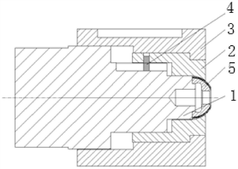
[0040] In this embodiment, the processed spherical parts are the left and right hemispheres used in a certain type of dynamic pressure motor, that is, the processed spherical parts are hemispherical parts, such as figure 2 As shown, the positioning fixture includes a mandrel 1, a positioning sleeve 2, a locking compression sleeve 3 and a positioning pin 4;

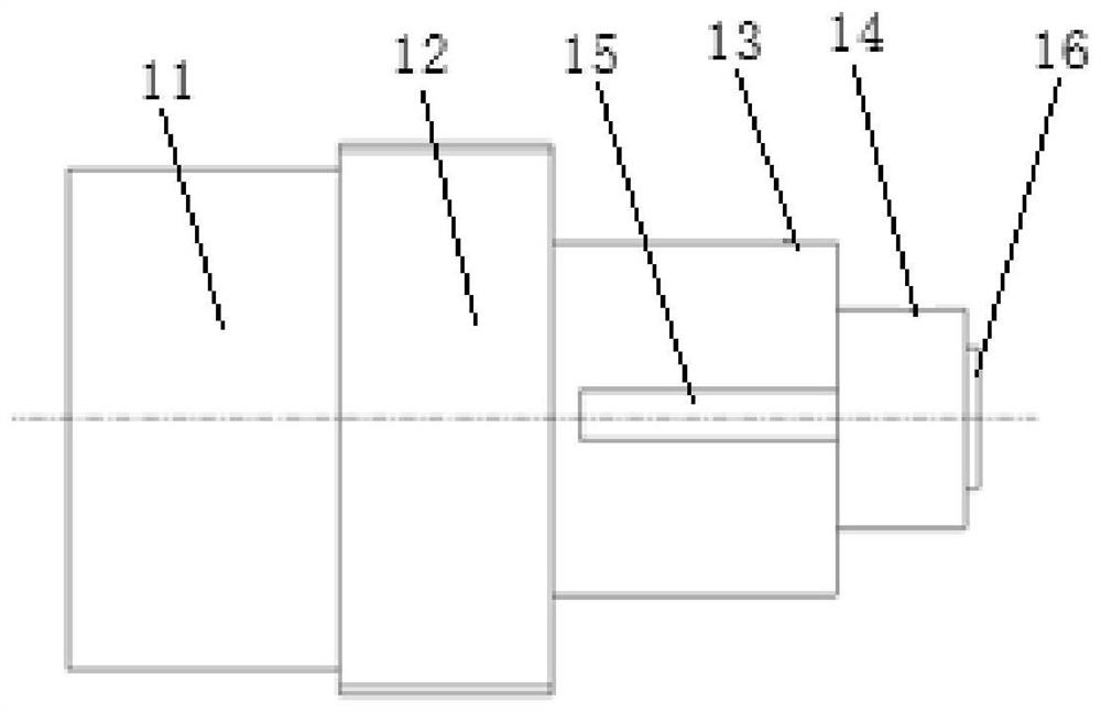
[0041] Such as figure 2 with image 3 As shown, the mandrel 1 includes a clamping section 11, a threaded connection section 12, a circumferential positioning section 13, and an axial positioning section 14 arranged in sequence; the clamping section 11 is used for clamping of a processing machine tool; Screw thread; On the circumferential positioning section 13, there is an opening positioning groove 15 along the axial direction; figure 1 The φ10 hole in the hole is a dismounting hole), so the end face of the axial positioning section in this embodiment is also provided with a columnar protrusion 16, and the outer diame...

Embodiment 2

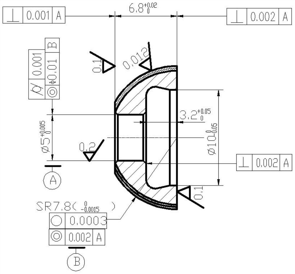
[0047] In this embodiment, the processed spherical part is a complete spherical part, and the structure of the positioning fixture adopted is basically the same as that of Embodiment 1. See figure 1 , the difference is that the end face of the axial positioning section is in contact with the spherical part in a different way, and the specific structure has the following two types:

[0048] 1: The end face of the axial positioning section is provided with a groove, and the opening of the groove is processed with a circular chamfer, and the outer spherical surface of the spherical part can be initially positioned through the circular chamfer.

[0049] 2: The end face of the axial positioning section is provided with a spherical groove, and the radius of curvature of the spherical groove matches the radius of the processed spherical part, which can ensure more accurate positioning.

[0050] Above two embodiments also have following optimization design:

[0051] 1. In order to en...


PUM


Abstract

The invention discloses a positioning fixture for processing spherical parts. The fixture not only has accurate positioning, but also does not cause damage to the outer spherical surface of the spherical part. The fixture includes a mandrel, a positioning sleeve, a locking pressure sleeve and a positioning pin; One end of the mandrel is clamped on the processing machine tool, and the end surface of the other end is used to contact the spherical part to be processed; the positioning sleeve is set on the mandrel, and cooperates with the outer spherical surface of the spherical part to be processed through the concave spherical surface set inside it; the positioning pin Arranged along the radial direction, one end is fixedly connected with the positioning sleeve, and the other end is inserted into the positioning sleeve; the inner locking compression sleeve is fitted outside the positioning sleeve, and is threadedly connected with the mandrel.

Description

technical field [0001] The invention relates to a positioning fixture, in particular to a positioning fixture for processing spherical parts. Background technique [0002] In the various processing processes of mechanical manufacturing, the workpiece must be in a suitable and correct position in the process system to ensure the processing quality and improve production efficiency. In order to make the workpiece in a suitable and correct position, the various process equipment used, Collectively referred to as fixtures. [0003] High-precision balls are the key basic components in precision ball bearings, ball screws, gyroscopes and precision measuring instruments. They occupy a very important position in the engineering field and are widely used in aviation, aerospace, petroleum, machinery and electronic appliances. The spherical error and surface roughness of the sphere directly affect the accuracy, life and reliability of the equipment. [0004] The left and right hemisp...

Claims


Application Information

Patent Timeline
Patent Type & Authority Patents(China)
IPC IPC(8): B23Q3/14B23Q3/00
CPCB23Q3/14B23Q3/00B23Q2703/10
Inventor 柳亚楠张昌星翁长志邵荔宁何亚飞谢东伟杨少辉周光
Owner XIAN AEROSPACE PRECISION ELECTROMECHANICAL INST
Why Eureka
Try Eureka