
Spindle cooling device for numerically-controlled machine tool

A technology for CNC machine tools and cooling devices, which is applied in metal processing machinery parts, maintenance and safety accessories, metal processing equipment, etc., and can solve the problems of poor spindle cooling effect and low efficiency of cooling source use.

Inactive Publication Date: 2021-01-05
杨晓成
View PDF11 Cites 0 Cited by
  • Summary
  • Abstract
  • Description
  • Claims
  • Application Information

AI Technical Summary

Problems solved by technology

[0004] Based on the technical problems of poor cooling effect on the spindle and low efficiency of the cold source in the prior art, the present invention proposes a spindle cooling device for CNC machine tools

Method used


Image

  • Spindle cooling device for numerically-controlled machine tool
  • Spindle cooling device for numerically-controlled machine tool
  • Spindle cooling device for numerically-controlled machine tool

Examples


Embodiment 1

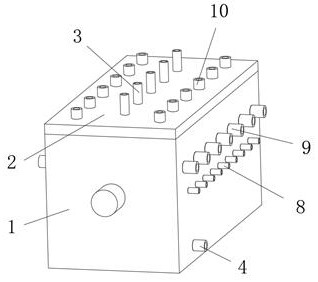
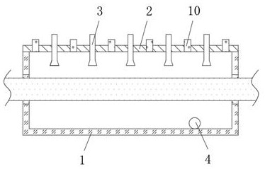
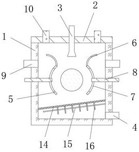
[0026] refer to Figure 1-4 , a spindle cooling device for a CNC machine tool, comprising a cooling box 1, the middle position between the two sides of the cooling box 1 is rotatably connected to the main shaft, the top of the cooling box 1 is fixed with a cover plate 2, and the top of the cover plate 2 is fixed with a horizontal The nozzles 3 are distributed equidistantly in the direction, the bottom end of the cooling box 1 is fixed with a liquid discharge pipe 4, and the two ends of the main shaft are fixed with arc-shaped stoppers 5 between the inner walls on both sides of the cooling box 1, and the stoppers The middle position of 5 is set to arch toward the end away from the main shaft, and the top of the limiter 5 is fixed with an arc-shaped flow guide 6, and the flow guide 6 is inclined upward toward the end far away from the main shaft, and the middle of the flow guide 6 The position is arched toward the end close to the main shaft, and both ends of the top of the cove...

Embodiment 2

[0030] refer to Figure 1-5 , a spindle cooling device for a CNC machine tool, the bottom between the inner walls of the two ends of the cooling box 1 is fixed with a filter screen plate 14 placed obliquely, and the filter screen plate 14 is inclined downward toward the end away from the drain pipe 4, the cooling box 1 One end close to the drain pipe 4 is located at the bottom of the filter screen plate 14, and a partition plate 15 is fixed. The inclination direction of the partition plate 15 and the filter screen plate 14 is the same. leave a gap;

[0031] The top outer wall of the partition 15 is fixed with cooling fins 16 distributed equidistantly, and the middle position of the cooling fins 16 is set to be arched towards the end close to the drain pipe 4, and the cooling fins 16 on the partition 15 are arranged to be distributed at intervals. The outer wall of one end of the heat sink 16 is located at the top and bottom of the partition 15 and is provided with a plurality...


PUM


Abstract

The invention belongs to the technical field of numerical control, particularly relates to a spindle cooling device for a numerically-controlled machine tool, and provides the following scheme for solving the problems that in the prior art, a spindle cooling device is poor in spindle cooling effect and low in cold source using efficiency. The spindle cooling device comprises a cooling box, a spindle is rotatably connected in the middle position between the two sides of the cooling box, a cover plate is fixed to the top of the cooling box, spray heads distributed at equal intervals in the horizontal direction are fixed to the top of the cover plate, a liquid discharging pipe is fixed to the bottom end of the cooling box, and limiting pieces of arc-shaped structures are fixed to the positions, located at the two ends of the spindle, between the inner walls of the two sides of the cooling box. The middle positions of the limiting pieces are arched towards one end far away from the spindle. According to the cooling device, through limiting and flow guiding of the limiting pieces, the cooling device makes full contact with the spindle for heat exchange, an air pipe is matched for blowing air from the middle position to upwards extrude hot steam and disperse heat all around, the actual cooling effect on the main shaft is improved, and the actual utilization effect on the cooling source is improved.

Description

technical field [0001] The invention relates to the technical field of numerical control, in particular to a spindle cooling device for a numerical control machine tool. Background technique [0002] Numerical control is the abbreviation of digital control. Numerical control technology is a method to control mechanical movement and processing process by using digital information. The early numerical control system is called hardware numerical control, which is composed of hardware circuits. Instead of being called a computer numerical control system, a CNC machine tool is a part of the application of the CNC system, where the machine tool spindle is the main part of the drive mechanism in the CNC machine tool. [0003] The spindle of the CNC machine tool will rotate at high speed during the actual working process. The CNC spindle will generate a lot of heat during high-speed rotation and friction. Long-term work will cause the deformation of the spindle and affect the workin...

Claims


Application Information

Patent Timeline
IPC IPC(8): B23Q11/12
CPCB23Q11/127
Inventor 杨晓成
Owner 杨晓成
Learn More