
Power-assisted manipulator capable of rotatably clamping

A technology of assisting manipulators and rotating clamps, applied in manipulators, program-controlled manipulators, chucks, etc., can solve the problems of large space occupation, not unique value, difficult to meet the grasping and transferring of heavy objects, etc., to increase the quality of heavy objects, The effect of reducing the size

Inactive Publication Date: 2021-01-05
지앙수위에다인베스트먼트컴퍼니리미티드
View PDF7 Cites 0 Cited by
  • Summary
  • Abstract
  • Description
  • Claims
  • Application Information

AI Technical Summary

Problems solved by technology

It uses the principle of leverage to easily transport heavy objects from one position to the desired designated position. In the prior art, power-assisted manipulators generally can only meet the requirements of grasping heavy objects in a single position and a single posture and the selection of the main cylinder The type is too large and some need to add counterweights, which occupy a large space and have certain limitations. It is difficult to grasp and transfer heavy objects in different positions and attitudes under the space requirements. For the actual workshop multi-layer shelves The complex working conditions of lifting heavy objects are not universal. The grabbing angles required for grabbing heavy objects placed on different layers of shelves are not unique, and the shelves in different workshops are not of uniform specifications, so different angles are required. In view of the versatility of the power-assisted manipulator for easy movement and the limitation of a single gripper, it is necessary to develop a power-assisted manipulator that saves space and meets the requirements of grabbing heavy objects at different positions and attitudes in the actual workshop.

Method used


Image

  • Power-assisted manipulator capable of rotatably clamping
  • Power-assisted manipulator capable of rotatably clamping
  • Power-assisted manipulator capable of rotatably clamping

Examples


Embodiment Construction

[0018] Embodiments of the present invention are described in detail below, and examples of the embodiments are shown in the drawings, wherein the same or similar reference numerals denote the same or similar elements or elements having the same or similar functions throughout. The embodiments described below by referring to the figures are exemplary only for explaining the present invention and should not be construed as limiting the present invention.

[0019] In describing the present invention, it should be understood that the terms "center", "longitudinal", "transverse", "length", "width", "thickness", "upper", "lower", "front", " Back", "Left", "Right", "Vertical", "Horizontal", "Top", "Bottom", "Inner", "Outer", "Axial", "Radial", "Circumferential", etc. The indicated orientation or positional relationship is based on the orientation or positional relationship shown in the drawings, and is only for the convenience of describing the present invention and simplifying the d...


PUM


Abstract

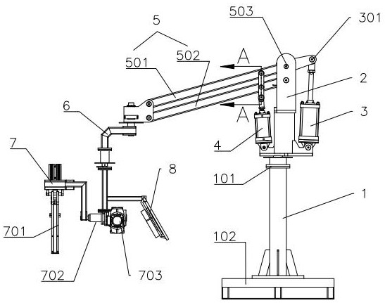
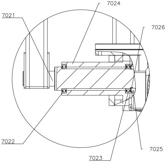
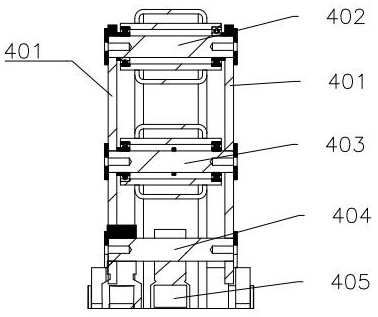
The invention relates to the technical field of mechanical equipment, and particularly provides a power-assisted manipulator capable of rotatably clamping. The power-assisted manipulator capable of rotatably clamping comprises a supporting stand column, a stand column rotating seat, a first air cylinder, a second air cylinder, first-stage arms, a second-stage arm and a clamping jaw assembly, the stand column rotating seat is installed at the top end of the supporting stand column, the first-stage arms are installed on the stand column rotating seat, one end of the first air cylinder and one end of the second air cylinder are hinged to the stand column rotating seat, the other end of the first air cylinder and the other end of the second air cylinder are connected with the first-stage armson the two sides of a connecting shaft respectively, and the clamping jaw assembly is mounted on the second-stage arm. The first air cylinder and the second air cylinder do opposite actions respectively, and through cooperation of the first air cylinder and the second air cylinder, the size of the first air cylinder is effectively reduced under the condition of the same lifting quality; and a clamping jaw is welded to a rotating shaft, a gear motor can drive the clamping jaw to complete 360-degree rotation, and after the clamping jaw rotates to the needed proper angle, the angle of the clamping jaw is fixed through a band-type brake of the motor, so that grabbing of heavy objects at different positions and in different postures in an actual workshop is met.

Description

technical field [0001] The invention relates to the technical field of mechanical equipment, in particular to a rotatable clamping assist manipulator. Background technique [0002] Power-assisted manipulator is a kind of power-assisted equipment used for labor-saving operation during material handling and installation. It uses the principle of leverage to easily transport heavy objects from one position to the desired designated position. In the prior art, power-assisted manipulators generally can only meet the requirements of grasping heavy objects in a single position and a single posture and the selection of the main cylinder The type is too large and some need to add counterweights, which takes up a lot of space and has certain limitations. It is difficult to grasp and transfer heavy objects in different positions and attitudes under the space requirements. For the actual workshop multi-layer shelves The complex working conditions of lifting heavy objects are not univer...

Claims


Application Information

Patent Timeline
Patent Type & Authority Applications(China)
IPC IPC(8): B25J9/10B25J15/02B65G47/90
CPCB25J9/10B25J15/02B65G47/90
Inventor 张建松解子胜刘飞
Owner 지앙수위에다인베스트먼트컴퍼니리미티드
Learn More