An automobile leaf spring suspension system with integrated brake air cylinder

A technology of spring suspension and automobile steel plate, which is applied to vehicle springs, elastic suspensions, springs, etc., can solve the problems of difficult layout and poor versatility, and achieve the effects of flexible layout, easy installation and high connection reliability

Active Publication Date: 2022-04-12
DONGFENG AUTOMOBILE COMPANY
View PDF0 Cites 0 Cited by
  • Summary
  • Abstract
  • Description
  • Claims
  • Application Information

AI Technical Summary

Problems solved by technology

[0003] The purpose of the present invention is to overcome the defects and problems of difficult layout and poor versatility existing in the prior art, and provide an automobile leaf spring suspension system with simple layout and good versatility integrated with a brake air reservoir

Method used


Image

  • An automobile leaf spring suspension system with integrated brake air cylinder
  • An automobile leaf spring suspension system with integrated brake air cylinder
  • An automobile leaf spring suspension system with integrated brake air cylinder

Examples


Embodiment 1

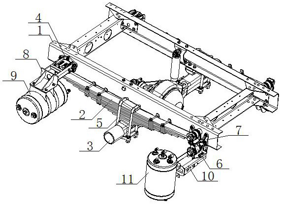
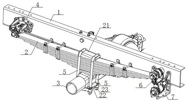
[0052] see figure 1 , figure 2 , an automobile leaf spring suspension system integrated with a brake air cylinder, comprising a vehicle frame 1, a leaf spring assembly 2 and an axle 3, the front end of the leaf spring assembly 2 is connected to the vehicle frame 1 through a fixed end support 4 The middle part of the leaf spring assembly 2 is connected with the axle 3 through the U-shaped bolt 5, the rear end of the leaf spring assembly 2 is connected with the upper part of the movable lifting lug 6, and the lower part of the movable lifting lug 6 is supported by the movable end. The seat 7 is connected with the vehicle frame 1, the fixed end support 4 is connected with the front air storage tank support 8, the front air storage tank support 8 is connected with the front air storage tank 9 in a horizontal arrangement, and the movable end support The seat 7 is connected with the rear air storage tank support 10, and the rear air storage tank support 10 is connected with the re...

Embodiment 2

[0054] Basic content is the same as embodiment 1, the difference is:

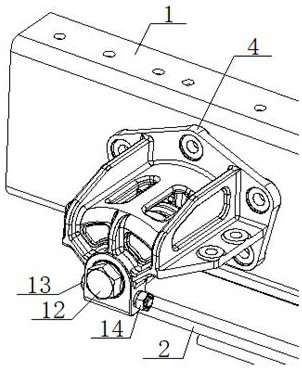
[0055] see figure 1 , figure 2 , image 3 , Figure 5 , Figure 6 , Figure 7 , Figure 8 , Figure 9, the fixed end support 4 includes a No. 1 riser 41, a No. 2 riser 42 and a No. 3 riser 43. The No. 1 riser 41 is connected to the side of the vehicle frame 1, and the lower part of the No. 1 riser 41 A first mounting boss 44 is provided, and a first threaded hole 45 is provided on the first mounting boss 44. One end of the second vertical board 42 and the third vertical board 43 is connected with the first vertical board 41, and the second vertical board 43 is connected with the first vertical board 41. A second installation boss 46 is connected between the other end of the vertical board 42 and the other end of the third vertical board 43, the second installation boss 46 is provided with a first installation hole 47, and the first installation hole 47 is sleeved with a first installation boss 46. ...

Embodiment 3

[0057] Basic content is the same as embodiment 1, the difference is:

[0058] see figure 1 , figure 2 , Figure 4 , Figure 10 , Figure 11 , Figure 12 , Figure 13 , Figure 14 , the movable end support 7 includes No. 5 vertical plate 71 and No. 5 horizontal plate 72 and No. 6 horizontal plate 73 connected on both sides thereof. The No. 5 vertical plate 71 is connected with the side of vehicle frame 1, and No. 5 The vertical plate 71 is provided with a third mounting boss 74, and the third mounting boss 74 is provided with a second threaded hole 75. The fifth horizontal plate 72 is connected with the lower wing surface of the vehicle frame 1, and the sixth horizontal plate The end of the plate 73 away from the No. 5 vertical plate 71 is provided with a fourth mounting boss 76, the fourth mounting boss 76 is provided with a third mounting hole 77, and the third mounting hole 77 is fitted with a second pin sleeve 78. The fixed pin shaft 17 is connected with the second...


PUM


Abstract

An automobile leaf spring suspension system integrated with a brake air cylinder, including a vehicle frame, a leaf spring assembly and an axle, the front end of the leaf spring assembly is connected to the vehicle frame through a fixed end support, and the leaf spring assembly The middle part is connected with the axle through U-shaped bolts, the rear end of the leaf spring assembly is connected with the upper part of the movable lifting lug, the lower part of the movable lifting lug is connected with the frame through the movable end support, and the fixed end support It is connected with the front air storage cylinder support, the front air storage cylinder support is connected with the front air storage cylinder in horizontal arrangement, the movable end support is connected with the rear air storage cylinder support, and the rear air storage cylinder support is vertical The arranged rear air reservoir is connected. This design is not only simple in layout, but also has good versatility.

Description

technical field [0001] The invention relates to the technical field of vehicle engineering, in particular to an automobile leaf spring suspension system integrated with a brake air reservoir, which is mainly suitable for reducing the difficulty of arrangement and improving the versatility. Background technique [0002] The air storage tank of the traditional bus chassis is generally arranged inside the frame, and space for components such as the luggage compartment, fuel tank, urea tank, and air-conditioning condenser must be reserved outside the frame. With the implementation of the National VI emission regulations, the length of the tail treatment of the National VI engines is generally too long, and there are strict requirements on the installation position, which occupies the space inside the frame. In the existing technology, the air storage tank is mostly arranged on the inside of the frame. The air storage tank is limited by the vehicle width, wheelbase, and rear trea...

Claims


Application Information

Patent Timeline
Patent Type & Authority Patents(China)
IPC IPC(8): B60G11/10B60T17/06
CPCB60G11/10B60T17/06B60G2202/11
Inventor 蔡涛陶小龙张健涛易小力鲁方强张茂霞孙玉海朱峰刘江明水海永王信马文波
Owner DONGFENG AUTOMOBILE COMPANY
Why Eureka
Try Eureka