Automatic moving hanging rack for electronic part production and using method

An electronic component, automatic moving technology, applied in transportation and packaging, conveyors, non-mechanical conveyors, etc., can solve problems such as high cost and inability to make full use of factory space, and achieve the effect of stable model

Active Publication Date: 2021-01-05
南京阿兹曼电子科技有限公司
View PDF7 Cites 0 Cited by
  • Summary
  • Abstract
  • Description
  • Claims
  • Application Information

AI Technical Summary

Problems solved by technology

[0003] The purpose of the present invention is to provide an automatic mobile hanger for the production of electronic parts and a method of use, to solve the problem of the existing intelligent equipment for parts transfer proposed in the above-mentioned background technology, the cost is relatively high, and the factory area cannot be fully utilized space problem

Method used


Image

  • Automatic moving hanging rack for electronic part production and using method
  • Automatic moving hanging rack for electronic part production and using method
  • Automatic moving hanging rack for electronic part production and using method

Examples


Embodiment 1

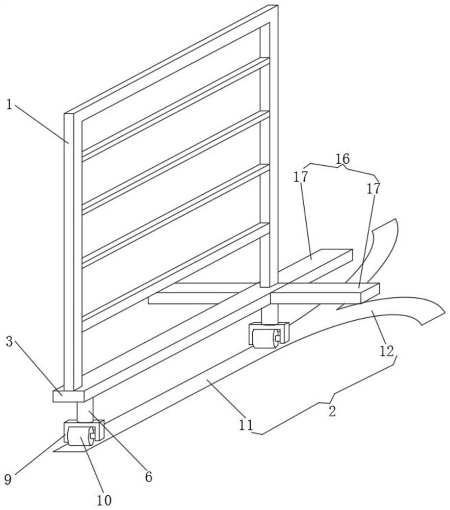
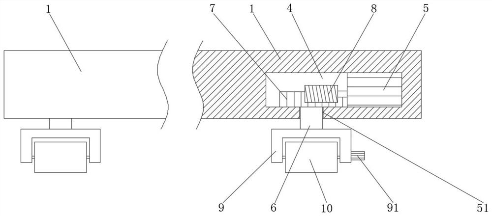
[0024] see Figure 1-4 , the present embodiment provides an automatic mobile hanger for the production of electronic parts, including a fixed frame 1 and a magnetic track 2, the bottom end of the fixed frame 1 is fixed with a crossbar 3, and an installation warehouse is provided inside one end of the crossbar 3 4. The steering motor 5 is installed inside the installation bin 4, and the inner wall of the bottom side of the installation bin 4 is provided with a rotating hole 51, and a rotating shaft 6 is installed inside the rotating hole 51, and a gear 7 is fixed on the top of the rotating shaft 6 inside the installation bin 4 , the power output shaft of the steering motor 5 meshes with the gear 7 through the screw mandrel 8. The screw mandrel 8 can not only realize the rotation of the gear 7, but also can realize the fixing effect on the gear 7 when the steering motor 5 is not excited, and can avoid the occurrence of a fixed frame. 1 Deviate from the track 2 direction movement...

Embodiment 2

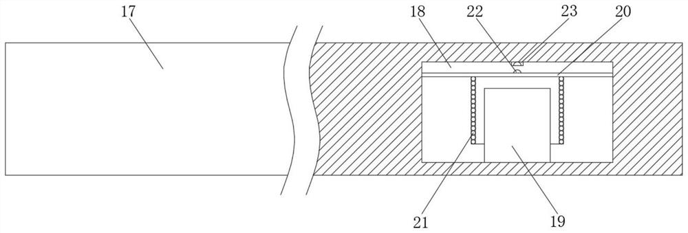
[0036] see figure 2 , On the basis of embodiment 1, a further improvement has been made: the inner wall of the bottom side of the equipment compartment 18 is fixed with a magnet 19, and the inner wall of the top side of the equipment compartment 18 is provided with a stretchable film 20 directly above the magnet 19, and the stretchable film 20 is close to the magnet 19 An induction coil 21 is fixed on one side, and the magnet 19 can apply magnetic forces in different directions to the induction coil 21 that generates an induced magnetic field, so that the stretchable film 20 can vibrate inside the equipment compartment 18, so that the contact 22 and the connection point 23 can be The frequency of the alternating current is contacted, so that the single-chip microcomputer 15 can obtain a high-level signal with a fixed frequency, and the signal at the information input end of the single-chip microcomputer 15 can be more stable.


PUM


Abstract

The invention discloses an automatic moving hanging rack for electronic part production and a using method thereof. The automatic moving hanging rack comprises a fixing rack and a magnetic track, wherein a transverse rod is fixed to the bottom end of the fixing rack, a mounting bin is formed in one end of the transverse rod, a steering motor is mounted in the mounting bin, a rotating hole is formed in the inner wall of the bottom side of the mounting bin, a rotating shaft is mounted in the rotating hole, a gear is fixed to the top end of the rotating shaft in the mounting bin, a power output shaft of the steering motor is engaged to the gear through a lead screw, rotating wheels are mounted at the bottom end of the rotating shaft and the ground at the end, far away from the mounting bin, of the transverse rod through the mounting rack, exciting coils are mounted in a straight way and a bent way and are connected to an alternating-current power source through wires, the exciting coils between the bent way and the straight way are connected through a relay, and the input end of the steering motor is connected to a single-chip microcomputer through a wire. By matching the devices in use, a transfer route can be customized, so that the space utilization rate of a plant area is increased, and the cost of transferring the hanging rack automatically is lowered.

Description

technical field [0001] The invention relates to the related technical field of electronic parts production equipment, in particular to an automatic mobile hanger for the production of electronic parts and a usage method. Background technique [0002] The production of electronic components often requires the use of hangers for product transfer. The existing intelligent equipment can realize the automatic operation of the hangers, but the cost is high, and high professional knowledge is required for installation and maintenance. If a specific route can be planned for the transfer of parts, it will undoubtedly be able to make the transfer of parts more efficient and maximize the utilization of factory space. Contents of the invention [0003] The purpose of the present invention is to provide an automatic mobile hanger for the production of electronic parts and a method of use, to solve the problem of the existing intelligent equipment for parts transfer proposed in the abov...

Claims


Application Information

Patent Timeline
Patent Type & Authority Applications(China)
IPC IPC(8): B65G54/02
CPCB65G54/02
Inventor 张强
Owner 南京阿兹曼电子科技有限公司
Why Eureka
Try Eureka