
Self-resetting steel frame beam-side column joint and construction method thereof

A steel frame beam, self-reset technology, applied in building components, earthquake resistance, building types, etc., can solve the problem of poor ductility and energy dissipation capacity of joint structures, large uncertainty of energy dissipation capacity and self-resetting performance of beam-column joints, etc. problems, to achieve superior superelasticity and energy dissipation capacity, improve structural ductility and energy dissipation capacity, and reduce residual deformation.

Pending Publication Date: 2021-01-05
XI'AN UNIVERSITY OF ARCHITECTURE AND TECHNOLOGY
View PDF0 Cites 3 Cited by
  • Summary
  • Abstract
  • Description
  • Claims
  • Application Information

AI Technical Summary

Problems solved by technology

[0004] Aiming at the technical problems existing in the prior art, the present invention provides a self-resetting steel frame beam-side column joint and its construction method to solve the energy consumption of the beam-column joint when memory alloy materials are used in the existing beam-column joint. The uncertainty of energy capacity and self-resetting performance is large, and the structural ductility and energy dissipation capacity of nodes are poor technical problems

Method used


Image

  • Self-resetting steel frame beam-side column joint and construction method thereof
  • Self-resetting steel frame beam-side column joint and construction method thereof
  • Self-resetting steel frame beam-side column joint and construction method thereof

Examples


Embodiment

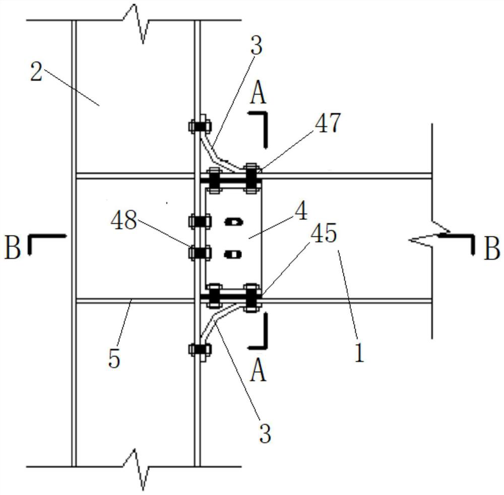
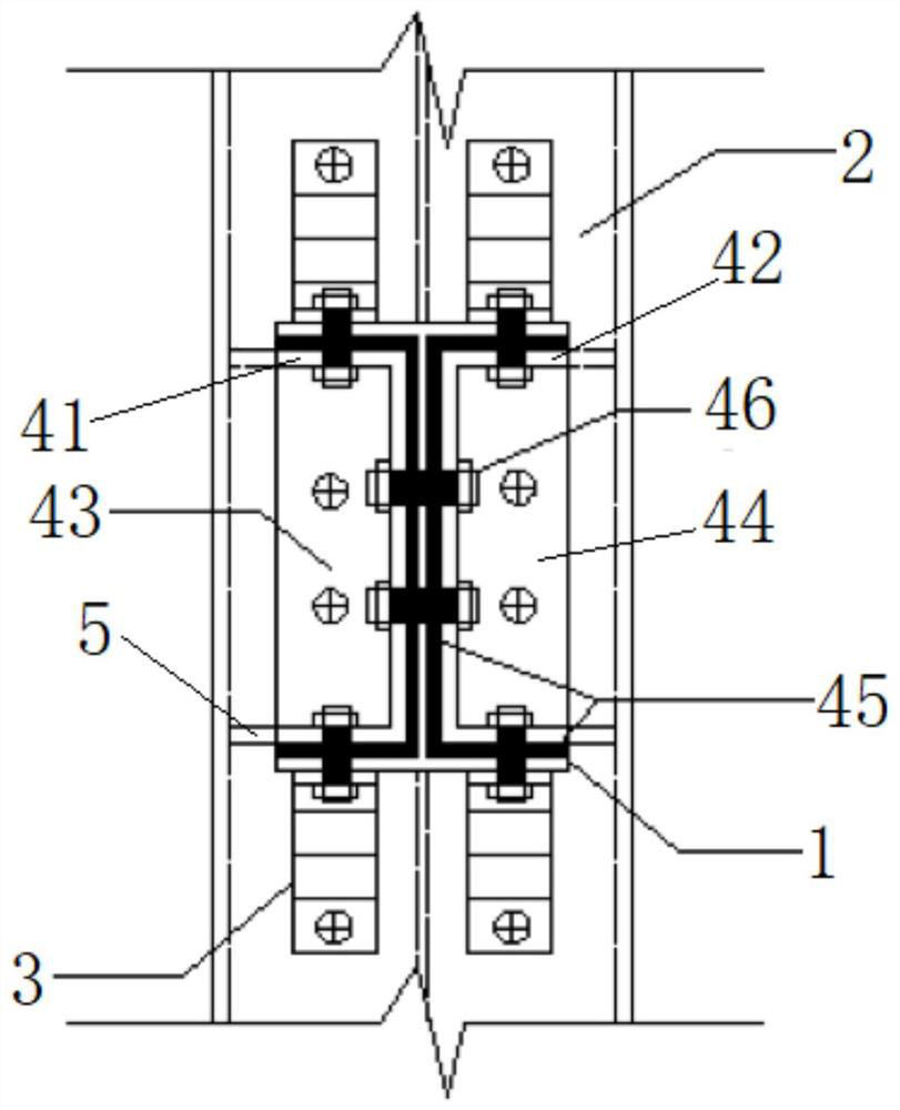
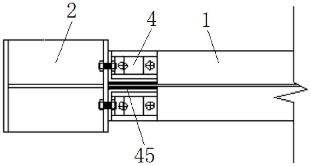
[0056]This embodiment provides a self-resetting steel frame beam-side column joint, including a steel column, a steel beam on one side of the steel column, a shape memory alloy bent steel plate connecting the flange of the steel column and the flange of the steel beam, and The frictional energy dissipator located at the web of the steel beam; the frictional energy dissipator includes an end plate connector set on the web of the steel beam and connected to the flange of the steel column, and a filling between the end plate connector and the steel beam web Energy-dissipating friction plates, high-strength bolts that pass through the web of the steel beam and connect the end plate connector, the energy-dissipating friction plate and the web of the steel beam together. The end plate connector includes connecting steel plates and channel steel fixed on the connecting steel plates , the web plate of the channel-shaped steel has oblong bolt holes; among them, the connecting steel plat...


PUM


Abstract

The invention provides a self-resetting steel frame beam-side column joint and a construction method thereof. The self-resetting steel frame beam-side column joint comprises a steel beam, wherein thesteel beam is horizontally arranged on one side of a steel column; a shape memory alloy plate is arranged between a flange of the steel beam and a flange of the steel column, and the shape memory alloy plate is arranged on the outer side of the flange of the steel beam; one end of the shape memory alloy plate is connected with the flange of the steel beam, and the other end of the shape memory alloy plate is connected with the flange of the steel column; and friction energy dissipaters are symmetrically arranged on the two sides of a web of the steel beam, one end of each friction energy dissipater is connected with the steel beam, and the other end of each friction energy dissipater is connected with the flange of the steel column. According to the self-resetting steel frame beam-side column joint and the construction method thereof, the shape memory alloy plate is arranged, and the self-resetting function of the joint is achieved by utilizing the plastic deformation of the shape memory alloy plate; and friction energy dissipation can be achieved between the friction energy dissipaters and the flange and the web of the steel beam, and the friction energy dissipaters and the shapememory alloy plate generate a synergistic effect to jointly absorb seismic energy at the joint, so that the structural ductility and energy dissipation capacity of the steel frame beam-side column joint are effectively improved, and the post-earthquake repair cost of the structure is reduced.

Description

technical field [0001] The invention belongs to the technical field of structural engineering, in particular to a self-resetting steel frame beam-side column joint and a construction method thereof. Background technique [0002] The traditional steel frame beam-column joints are mainly welded to form rigid joints, but the post-earthquake joints are prone to brittle failure, and the structural ductility and energy dissipation capacity are poor, and the residual deformation is large, making post-earthquake repairs difficult and costly; Based on the development of performance-based seismic design concepts, the functional requirements of improving structural recoverability by controlling the residual deformation of structures after earthquakes have gradually attracted the attention of scholars at home and abroad. [0003] At present, the self-resetting seismic structural system mainly integrates the beam and column components into a whole by introducing post-tensioning prestress...

Claims


Application Information

Patent Timeline
Patent Type & Authority Applications(China)
IPC IPC(8): E04B1/58E04B1/24E04B1/98E04H9/02
CPCE04B1/5812E04B1/2403E04B1/98E04H9/021E04H9/024E04B2001/2406E04B2001/2448
Inventor 崔柳王社良张航
Owner XI'AN UNIVERSITY OF ARCHITECTURE AND TECHNOLOGY
Learn More