
Built-in portal rigid frame structure for reinforcing existing masonry building and construction method of built-in portal rigid frame structure

A portal frame and architectural technology, which is applied in building construction, construction, building maintenance, etc., can solve the problems of failure to meet the protection requirements of cultural relics and historical buildings, large distance between transverse walls of open structures, sudden changes in upper and lower rigidity, etc. problem, to achieve the effect of avoiding sudden changes in torsion and stiffness of the weak layer, reducing plane torsion, and balancing the stiffness of the upper and lower layers

Pending Publication Date: 2021-01-05
CHINA ACAD OF BUILDING RES +1
View PDF6 Cites 0 Cited by
  • Summary
  • Abstract
  • Description
  • Claims
  • Application Information

AI Technical Summary

Problems solved by technology

[0005] The purpose of the present invention is to provide a built-in portal frame structure and its construction method for strengthening the existing masonry buildings, so as to solve the problems caused by the large distance between the transverse walls of the open structure, the sudden change of the rigidity of the upper and lower sides of the building with a large opening on the bottom floor, and the occurrence of earthquakes. It is prone to torsion; the existing reinforcement methods have different degrees of changes to the facade of the building, which cannot meet the technical problems of the protection requirements for the facade of cultural relics and historical buildings

Method used


Image

  • Built-in portal rigid frame structure for reinforcing existing masonry building and construction method of built-in portal rigid frame structure
  • Built-in portal rigid frame structure for reinforcing existing masonry building and construction method of built-in portal rigid frame structure
  • Built-in portal rigid frame structure for reinforcing existing masonry building and construction method of built-in portal rigid frame structure

Examples


Embodiment Construction

[0035] In order to make the technical means, innovative features, goals and effects achieved by the present invention easy to understand, the present invention will be further described below.

[0036] The examples described here are specific specific implementations of the present invention, and are used to illustrate the concept of the present invention. They are all explanatory and exemplary, and should not be construed as limiting the implementation of the present invention and the scope of the present invention. In addition to the embodiments described here, those skilled in the art can also adopt other obvious technical solutions based on the claims of the application and the contents disclosed in the description, and these technical solutions include adopting any obvious changes made to the embodiments described here. Replacement and modified technical solutions.

[0037] In the description of the present invention, it should be noted that the terms "upper", "lower", "i...


PUM


Abstract

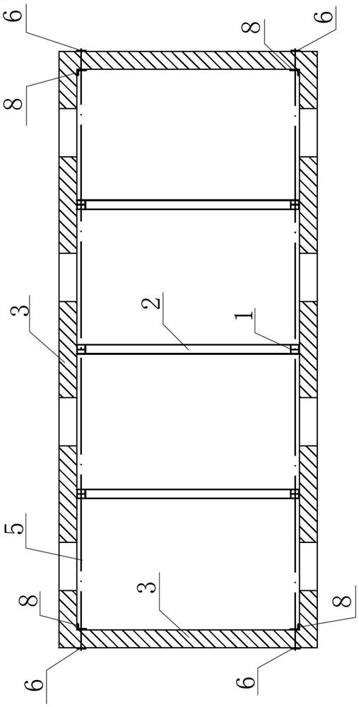
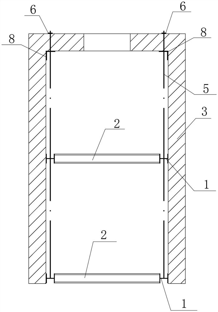
The invention discloses a built-in portal rigid frame structure for reinforcing an existing masonry building and a construction method of the built-in portal rigid frame structure, and belongs to thefield of building construction. The structure comprises portal rigid frame columns and portal rigid frame beams, wherein the portal rigid frame columns are connected to the inner side of an original masonry wall, the portal rigid frame beams are connected to the bottom of an original beam plate, and the ends of the portal rigid frame beams are connected with the portal rigid frame columns. According to the structure and the method, on the premise that an original external facade effect of a building is kept, a distance between transverse walls is effectively reduced, the rigidity of upper andlower layers is adjusted, and a structural system is optimized. The portal rigid frame system has the advantages of being simple in structure, clear in force transmission path and the like, and damageto an original structure is reduced while the construction efficiency can be improved by adopting an assembly type installation method. A built-in portal rigid frame reinforcing technology has obvious advantages when applied to building reinforcing transformation. The structure is low in construction difficulty, high in reinforcing efficiency and flexible in reinforcing position arrangement, andcan be applied to reinforcing projects with external facade protection requirements.

Description

technical field [0001] The invention belongs to the field of building construction, in particular to a built-in portal frame structure for strengthening existing masonry buildings and a construction method thereof. Background technique [0002] The masonry structure is widely used in our country because of its low cost. However, due to the long history of construction, the distance between the transverse walls of some masonry buildings is relatively large, and there are problems such as weak connection between longitudinal and transverse walls, poor integrity, and poor out-of-plane stability of the walls. Due to the large distance between the transverse walls, the value of the influence coefficient ϕ is too small when checking the vertical pressure bearing of the masonry wall, which leads to insufficient vertical bearing capacity of the wall. Some shops with masonry structure have long open doors on the side facing the street on the ground floor, while the upper floors are ...

Claims


Application Information

Patent Timeline
Patent Type & Authority Applications(China)
IPC IPC(8): E04G23/02
CPCE04G23/0222
Inventor 尹保江程绍革丁相宜宗立阳杜媛媛郝光钦
Owner CHINA ACAD OF BUILDING RES
Learn More