
Mixer integration device, DPF system and vehicle

A technology of integrated devices and mixers, which can be used in mufflers, exhaust devices, machines/engines, etc., to solve problems such as fuel droplet leakage, and to increase exhaust pressure, increase exhaust temperature, increase flow rate and temperature. Effect

Active Publication Date: 2021-01-05
FAW JIEFANG AUTOMOTIVE CO
View PDF5 Cites 1 Cited by
  • Summary
  • Abstract
  • Description
  • Claims
  • Application Information

AI Technical Summary

Problems solved by technology

[0004] However, because the fuel is difficult to fully break up the gasification heat release when the temperature condition is low and the high-temperature exhaust gas flow rate is small, so the leakage of fuel droplets and the coking and carbonization of incomplete combustion often occur in the downstream of the injection.

Method used


Image

  • Mixer integration device, DPF system and vehicle
  • Mixer integration device, DPF system and vehicle
  • Mixer integration device, DPF system and vehicle

Examples


Embodiment 1

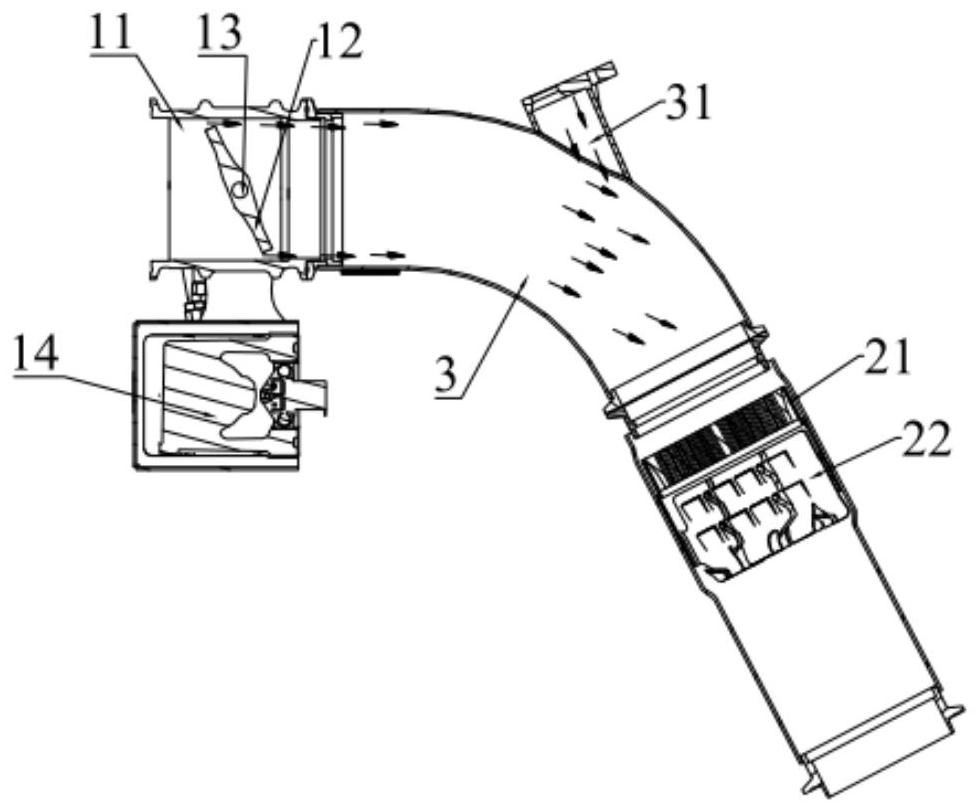
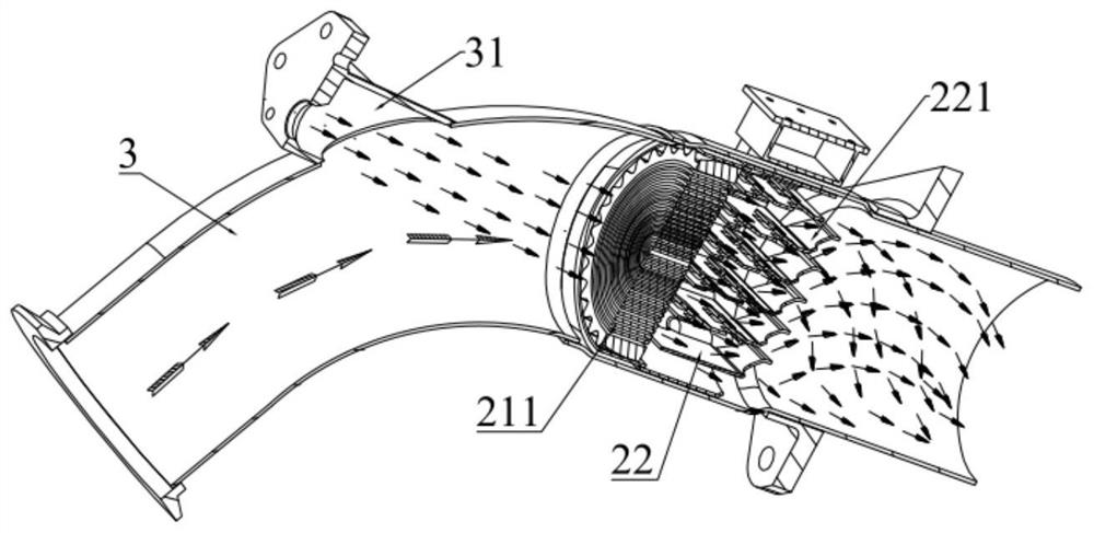
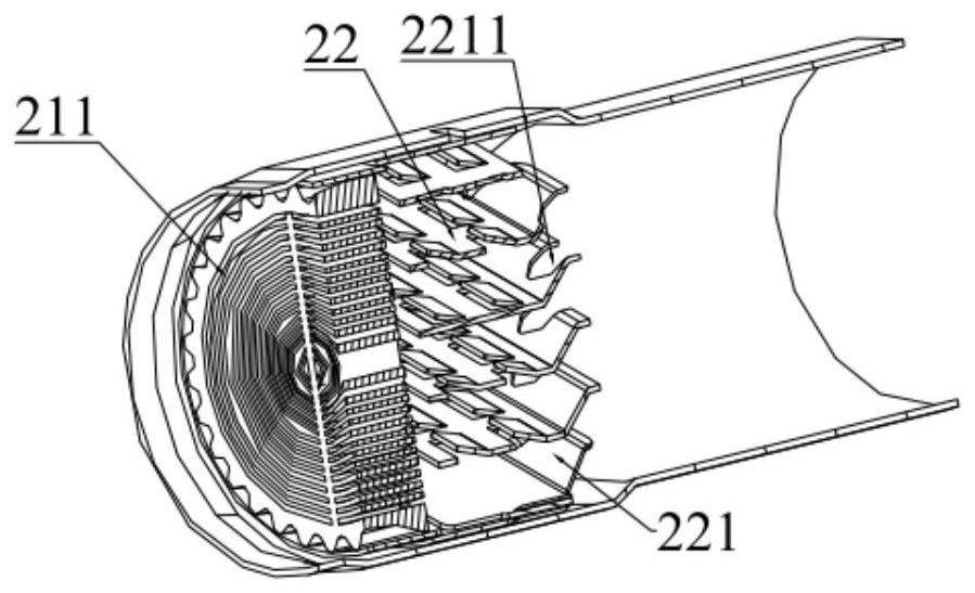
[0036] The embodiment of the invention discloses a mixer integrated device, such as Figure 1-Figure 4 As shown, the mixer integrated device includes an exhaust temperature management valve 1 and a mixing assembly 2 , and the mixing assembly 2 is arranged downstream of the exhaust temperature management valve 1 . Specifically, the exhaust temperature management valve 1 includes a valve body 11, a valve plate 12 and a driving member 14. The valve plate 12 is rotatably arranged in the valve body 11, and a gap for gas to pass is formed between the valve plate 12 and the valve body 11. The driving member The output end of 14 is in drive connection with the valve plate 12 to drive the valve plate 12 to rotate to a preset position. The mixing assembly 2 is configured to mix gas and fuel.

[0037] A mixer integrated device disclosed in the present invention can reduce the flow rate of gas by setting the valve plate 12 and turning the valve plate 12 to a preset position (preset openi...

Embodiment 2

[0060] In this embodiment, the parts that are the same as in the first embodiment are given the same reference numerals, and the same text descriptions are omitted.

[0061] Compared with the first embodiment, the integrated mixer device provided by this embodiment has the following difference: the preset position includes a first position and a second position, and the valve plate 12 reciprocates between the first position and the second position. According to this setting, the adjustment of the opening degree is realized through the reciprocating movement of the valve plate 12, which can disturb the air flow, improve the mixing uniformity of gas and fuel and the ability to resist steady-state crystallization. The first position may be a position where the valve plate 12 is closed, and the second position may be a position where the valve plate 12 is fully opened, and the valve plate 12 disturbs flow through continuous opening and closing movement. It should be noted that thi...


PUM


Abstract

The invention discloses a mixer integrated device, a DPF system and a vehicle, and relates to the technical field of vehicle tail gas treatment. The mixer integrated device comprises an exhaust temperature management valve and a mixing assembly, the exhaust temperature management valve comprises a valve body, a valve sheet and a driving part, the valve sheet is rotatably arranged in the valve body, a gap allowing gas to pass through is formed between the valve sheet and the valve body, and the output end of the driving part is in transmission connection with the valve sheet so as to drive thevalve plate to rotate to a preset position; and the mixing assembly is fixedly connected to the downstream of the exhaust temperature management valve, and the mixing assembly is configured to mix thegas and fuel. The mixer integrated device can meet the requirements of the mixing assembly on exhaust flow and temperature under different working conditions, and also can have the cleaning functionon the inner wall of a pipeline.

Description

technical field [0001] The invention relates to the technical field of vehicle exhaust gas treatment, in particular to a mixer integration device, a DPF system and a vehicle. Background technique [0002] As the NOx limit continues to become stricter, extremely high requirements are placed on the mixing uniformity and crystallization resistance of fuels (urea, fuel oil, etc.). At the same time, the low-temperature and light-load working conditions of the vehicle require the fuel to have extremely high uniformity and evaporation rate even at low temperature and low flow, which requires the installation of a mixer to adapt to high and low temperature, high and low flow conditions. [0003] At the same time, the regulations have increased the limit requirements on the quantity and quality of particulate matter, so a diesel particulate filter (DPF) should be installed on the basis of the selective catalytic reduction post-processor (SCR). Since the DPF post-processor needs to a...

Claims


Application Information

Patent Timeline
Patent Type & Authority Applications(China)
IPC IPC(8): F01N3/025F01N3/28F01N3/20
CPCF01N3/0253F01N3/2892F01N3/2013F01N3/2066F01N2610/02Y02A50/20
Inventor 黄凯朱光贞杨泽辰王科星陈景瑞
Owner FAW JIEFANG AUTOMOTIVE CO
Learn More