
Semi-automatic tank car loading arm and control method thereof

A semi-automatic, loading and unloading arm technology, applied in container filling method, container discharge method, gas/liquid distribution and storage, etc., can solve the problems of frequent operation, time-consuming, low efficiency, etc. time, improve the efficiency of loading and unloading vehicles, and reduce the difficulty of docking

Active Publication Date: 2021-01-05
JARI AUTOMATION CO LTD CHINA
View PDF7 Cites 5 Cited by
  • Summary
  • Abstract
  • Description
  • Claims
  • Application Information

AI Technical Summary

Problems solved by technology

[0004] (1) It is difficult for the operator to pull the force of the vertical pipe to drive the inner arm to rotate around the first rotary joint, and it often requires another operator to assist one person to push the inner arm to complete the docking of the loading arm and the tanker; (2) Loading and unloading After the docking of the arm and the tank car is completed, procedures such as nitrogen purging, leak detection, pressure relief, pre-cooling, filling, purging, and arm disassembly need to be carried out. A total of 6 valves on the traditional loading arm need to be manually rotated more than 10 times. Frequent operation, time-consuming and labor-intensive
(3) The vertical pipe section of the loading and unloading arm will tilt downward due to the action of gravity in the natural state. When docking with the tanker, the operator needs to lift it up and maintain it in a horizontal state. The operation is laborious and difficult to maintain, and the loading and unloading arm and the tank are added Difficulty and time of car docking
(4) The loading and unloading arm and the tank car are connected by a loose flange. Each time the docking is removed, 8 bolts and 16 nuts need to be screwed, which takes a lot of time and is inefficient

Method used


Image

  • Semi-automatic tank car loading arm and control method thereof
  • Semi-automatic tank car loading arm and control method thereof
  • Semi-automatic tank car loading arm and control method thereof

Examples


Embodiment Construction

[0032] The present invention will be further introduced below in conjunction with the accompanying drawings and specific embodiments.

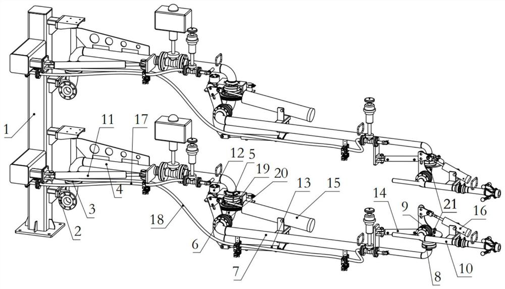
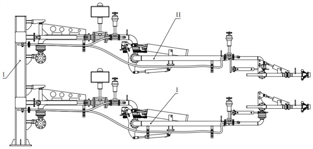
[0033] combine Figure 1-Figure 3 , a semi-automatic tank truck loading and unloading arm and its control method of the present invention, comprising a column 1, a liquid phase arm I and a gas phase arm II; Inner arm 4, outer arm 7, vertical pipe 10, four hydraulic drive mechanisms 11-14, two spring balance mechanisms 15-16, nitrogen purge system 17, exhaust system 18, five cryogenic rotary joints 3 / 5 / 6 / 8 / 9.

[0034] The inlet connector 2 is fixed on the column 1, and the inlet connector 2 is connected to one end of the inner arm 4 through the first rotary joint 3; the inner arm 4 is rotatably connected to the column 1 through the connector; the inner arm 4 The other end is connected to one end of the three-inch right-angle elbow 19 by the second rotary joint 5; the other end of the three-inch right-angle elbow 19 is connected to the eleven...


PUM


Abstract

The invention discloses a semi-automatic tank car loading arm and a control method thereof. The semi-automatic tank car loading arm comprises a stand column, a liquid-phase arm and a gas-phase arm. The liquid-phase arm and the gas-phase arm each comprise an inlet connecting piece, an inner arm, an outer arm, a vertical pipe, a pneumatic power assisting system, a nitrogen purging system, an emptying system, spring balance mechanisms, hydraulic driving mechanisms and low-temperature rotary joints. For each arm, the inlet connecting piece is fixed to the stand column and connected with the innerarm through a first rotary joint; the inner arm is connected with the stand column; the inner arm, a second rotary joint, a right-angled elbow, a third rotary joint, the outer arm, a fourth rotary joint, a right-angled elbow, a fifth rotary joint and the vertical pipe are connected in sequence; the nitrogen purging system and the emptying system are respectively arranged on the inner arm and the outer arm; the two spring balance mechanisms are arranged between the third rotary joint and the outer arm, as well as between the fifth rotary joint and the vertical pipe respectively; and the hydraulic driving mechanisms are arranged between the stand column and the inner arm, at the second rotary joint, between the third rotary joint and the outer arm and between the fourth rotary joint and thevertical pipe respectively. Operation efficiency of the loading arm can be improved.

Description

technical field [0001] The invention relates to a fluid loading and unloading device, in particular to a semi-automatic tank truck loading and unloading arm and a control method thereof. Background technique [0002] LNG (Liquefied Natural Gas) is a clean and efficient energy source, which helps my country realize the diversification of energy supply and ensure energy security. With the rapid development of the LNG industry, the traditional pipeline transportation mode is not enough to meet the needs of a large number of small and medium-sized users. Because of its strong flexibility and economy, the LNG tanker has been used as the main sales vehicle at each receiving station to make up for the lack of pipeline transportation. [0003] With the continuous increase of LNG consumption in my country, the number and scale of emergency reserve peak-shaving stations continue to increase, and the demand for tanker transportation speed continues to increase. As the intermediate equ...

Claims


Application Information

Patent Timeline
Patent Type & Authority Applications(China)
IPC IPC(8): F17C13/00
CPCF17C13/00
Inventor 胡旭杰周鑫华宋新伟苗增陈睿杲赛龙姚贵昌顾曙光
Owner JARI AUTOMATION CO LTD CHINA
Learn More