Automobile headlamp

A technology for automobile headlights and high beams, which is applied to headlights, motor vehicles, road vehicles, etc., can solve problems such as affecting the heat dissipation effect of the light source, reducing the photoelectric efficiency of the light source, and failing to achieve ultra-high beam lighting requirements.

Active Publication Date: 2021-01-05
GUANGZHOU UNIONLUX ELECTRONICS TECH CO LTD
View PDF15 Cites 5 Cited by
  • Summary
  • Abstract
  • Description
  • Claims
  • Application Information

AI Technical Summary

Problems solved by technology

Since the heat conduction channels of the two light sources basically overlap, this seriously affects the heat dissipation effect of the light source
[0003]In addition, in order to improve the light collection efficiency and optical effect of the light-emitting lens, the distance between the two light sources in the vertical direction should not be too large. The thickness of the heat dissipation substrate between them is limited, which also affects the heat dissipation effect of the

Method used


Image

  • Automobile headlamp
  • Automobile headlamp
  • Automobile headlamp

Examples


Embodiment 1

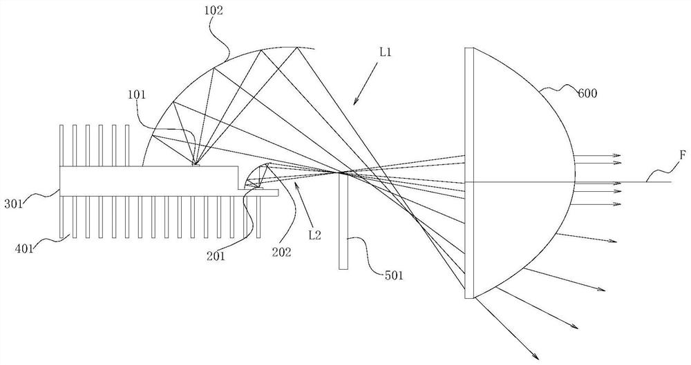
[0039] Such as figure 1 As shown, Embodiment 1 provides an automobile headlamp, including a heat dissipation substrate 301 , a low beam incident optical system, a high beam incident optical system, a light output device 600 , a far and low beam conversion device 501 , and a heat dissipation fin 401 .

[0040] In order to facilitate the understanding of the automobile headlamp provided in Embodiment 1, its application process will be described below first. When the automobile headlamp is in use, the low-beam incident optical system and the high-beam incident optical system are always on. Both the low beam L1 generated by the low beam incident optical system and the high beam L2 produced by the high beam incident optical system are emitted by the light output device 600 . The far and near light switching in Embodiment 1 is realized by the far and near light conversion device 501 . When low beam lighting is required, the low beam incident optical system generates low beam L1 an...

Embodiment 2

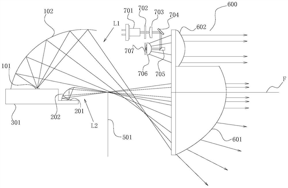
[0050] Such as figure 2 As shown, the present embodiment 2 provides an automobile headlight, which is improved on the scheme of embodiment 1. The automobile headlamp includes a heat dissipation substrate 301 , a low beam incident optical system, a high beam incident optical system, a light output device 600 , and a high and low beam conversion device 501 . In order to achieve ultra-long-distance lighting effects, an auxiliary high-beam incident optical system is added in Embodiment 2 of the present application.

[0051] Wherein, the light output device 600 includes a first light output lens 601 and a second light output lens 602, and the first light output lens 601 is located below the second light output lens 602; the first light area and the second light area It is located on the first light output lens 601, and the area occupied by the first light area and the second light area is formed after the first light output lens 601 removes part of its upper end structure; the th...

Embodiment 3

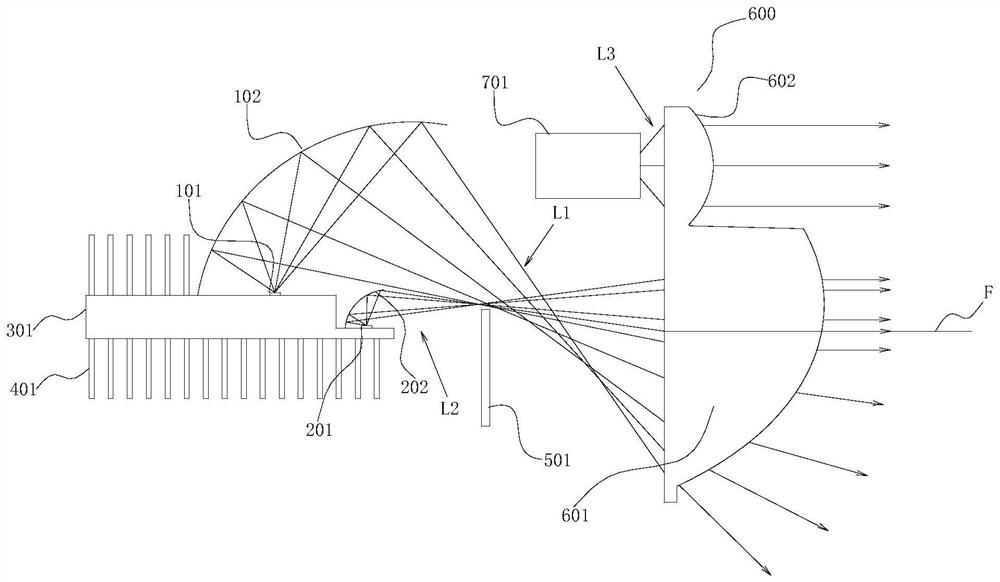
[0057] Such as image 3 As shown, Embodiment 3 provides an automobile headlight, which is improved on the solution of Embodiment 1, and its general configuration is basically the same as that of Embodiment 2. The automobile headlamp includes a heat dissipation substrate 301, a low beam incident optical system, a high beam incident optical system, a light output device 600, a far and low beam conversion device 501, a cooling fin 401, and an auxiliary high beam incident optical system. Different from Embodiment 2, the auxiliary high beam light source in Embodiment 3 is an LED light source.

[0058] Specifically, the auxiliary high beam incident optical system is used to generate the auxiliary high beam L3, the auxiliary high beam incident optical system includes an auxiliary high beam light source 701, and the auxiliary high beam L3 emitted by the LED light source is incident on the second output light lens 602 . The second light output lens 602 is used to collect the auxiliar...


PUM


Abstract

The invention relates to the technical field of automobile lighting, and provides an automobile headlamp which comprises a low-beam incident optical system for generating a low-beam light beam, a distance light incident optical system used for generating a distance light beam, a heat dissipation substrate having one side provided with the low-beam incident optical system and the distance light incident optical system, and a light emitting device used for collecting the low-beam light beam and the distance light beam and outputting the low-beam light beam and the high-beam light beam. The low-beam light beam and the distance light beam respectively form a first light area and a second light area on the light incident surface of the light emitting device, the second light area is arranged above the first light area, and the first light area and the second light area are partially overlapped; and a distance light and low beam conversion device is arranged between the heat dissipation substrate and the light emitting device. According to the invention, local heat accumulation of the heat dissipation substrate can be avoided, the heat dissipation efficiency is improved, the light collection rate of the light emitting device can be improved, and the ultra-long-distance lighting effect can be achieved.

Description

technical field [0001] The present invention relates to the technical field of automobile lighting, and more specifically, to an automobile headlamp. Background technique [0002] The two light sources of the low beam light source and the high beam light source of the lens headlights in the prior art are respectively arranged on both sides of the heat dissipation substrate. All the heat is exported through the same heat dissipation substrate. Since the heat conduction channels of the two light sources basically overlap, this seriously affects the heat dissipation effect of the light source. [0003] In addition, in order to improve the light collection efficiency and optical effect of the light-emitting lens, the distance between the two light sources in the vertical direction should not be too large, which will inevitably lead to the limitation of the thickness of the heat dissipation substrate between the far and near light sources, which also affects the front The heat ...

Claims


Application Information

Patent Timeline
IPC IPC(8): F21S41/25F21S41/30F21S45/47B60Q1/04F21W107/10F21Y115/10
CPCF21S41/25F21S41/30F21S45/47B60Q1/04F21W2107/10F21Y2115/10
Inventor 胡世雄黄成陈国平
Owner GUANGZHOU UNIONLUX ELECTRONICS TECH CO LTD
Why Eureka
Try Eureka