Improved soil saturation water conductivity detection system

A detection system and technology of hydraulic conductivity, applied in the field of improved soil saturated hydraulic conductivity detection, can solve the problems of experimental error, large experimental error, inaccurate calculation results of saturated hydraulic conductivity, etc., so as to avoid experimental errors and achieve accurate results. , The effect of preventing splashing and evaporation

Pending Publication Date: 2021-01-05
陕西地建土地工程技术研究院有限责任公司
View PDF7 Cites 1 Cited by
  • Summary
  • Abstract
  • Description
  • Claims
  • Application Information

AI Technical Summary

Problems solved by technology

[0005] When performing detection, it is necessary for the experimenter to count the time according to the timer when the metering valve is opened or closed. The reaction and operation time of the experimenter will cause experimental errors; These experimental errors will cause inaccurate calculation results of saturated hydraulic conductivity

Method used


Image

  • Improved soil saturation water conductivity detection system
  • Improved soil saturation water conductivity detection system
  • Improved soil saturation water conductivity detection system

Examples


Embodiment 1

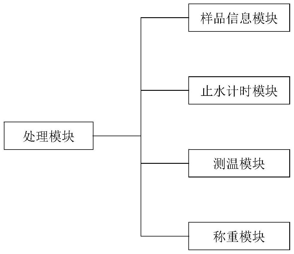
[0044] Such as figure 1 An improved soil saturated hydraulic conductivity detection system includes: a sample information module, which is used to collect the length, cross-sectional area and experimental water level difference data of the soil sample to be detected; add experimental water to the detection system and The experimental water of infiltration flows into the water container 5 of the lower floor, and is weighed by a miniature electronic scale 9;

[0045] Water-stop timing module, the water-stop timing module communicates with the sample information module; and detects the penetration time of the water passing through the soil in the sample information module; the penetration time t is determined according to the weight of the water in the water container, when When the weight of the water is 100-150g, it can be closed manually, or this part can be set to automatic sensing. The system program is set to automatically close and time when the weight of the water in the ...

Embodiment 2

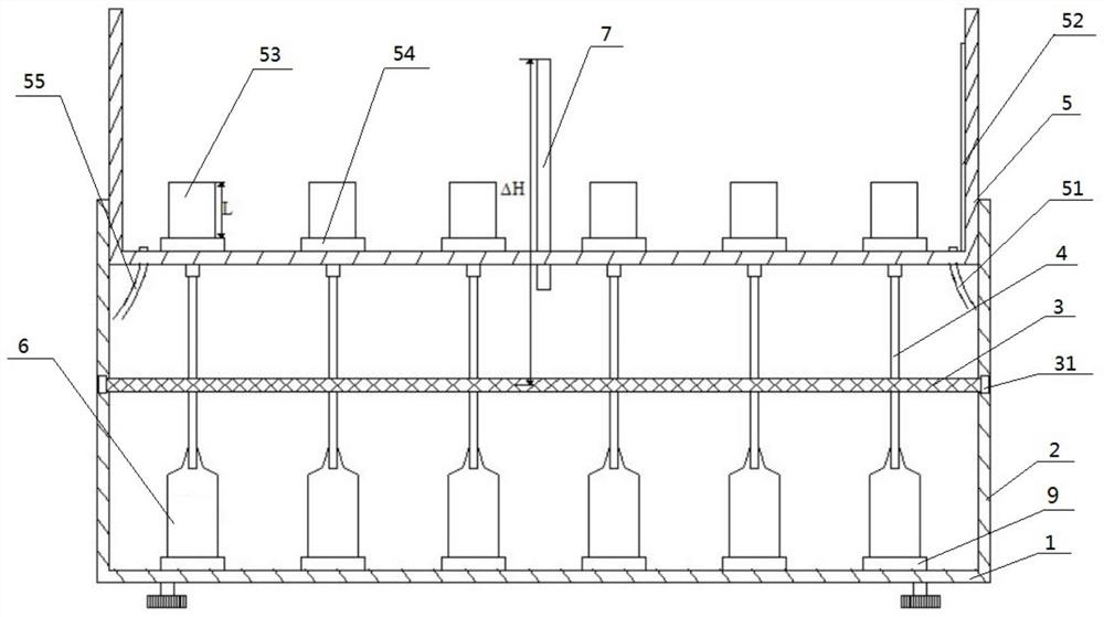
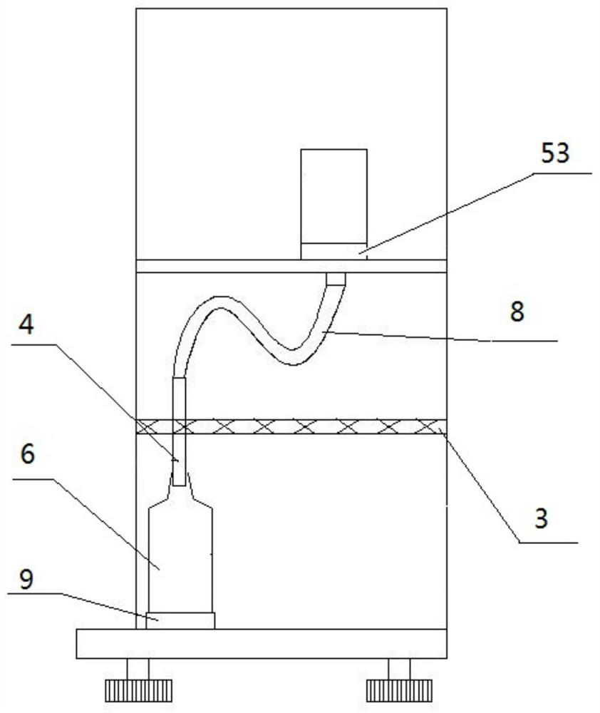
[0060] Such as figure 2 with image 3 The sample information module shown includes: a detection frame formed by a support plate I1 arranged horizontally and a support plate II2 fixedly connected to both sides of the support plate I1, a water container 5 arranged on the top of the detection frame; two support plates The plate II2 is fixed on both sides of the support plate I1 to form a detection frame, and the water container 5 is used to pass water for the experiment, specifically, a water inlet 55 and a water outlet 51 are provided on both sides of the bottom of the water container 5, Inject experimental water into the water container 5 through the water inlet 55, and the water after the experiment is discharged through the water outlet;

[0061] A plurality of sample collectors 54 for placing sample ring cutters 53 in the water container 5, the bottom of the sample receiver 54 is connected with the ∽ tube 8 and the latex tube 4, and one end of the ∽ tube 8 passes through t...

Embodiment 3

[0067] On the basis of embodiment 2, in order to ensure that after the latex tube is opened by the first splint and the second splint, the timing function can be performed in time after the latex tube is passed through water, such as Figure 4 The timing assembly includes a timer 352 fixed on the first splint 32, buttons 3521 are arranged on the corresponding two sides of the timer 352, and buttons 3521 are fixed on the second splint 34 facing away from the timer 352 for touching the button. The metal sheet I351 of 3521, the metal sheet I351 is connected with the metal sheet II through the connecting plate, the metal sheet II is arranged above the first splint 32 provided with the timer 352, and the timer 352 is located between the metal sheet I351 and the metal sheet II between. When in use, when the first splint and the second splint are in the clamping state, the latex tube is in the closed state at this time, the button 3521 is touched by the metal sheet I351, and the time...


PUM


Abstract

The invention relates to an improved soil saturation water conductivity detection system. The system comprises a sample information module, a water stop timing module, a temperature measurement module, a weighing module and a processing module. The sample information module in the system records the number, the length, the cross sectional area and the experimental water level difference of a soilsample; the water stop timing module records experiment time; the temperature measurement module detects the temperature of the experimental water and determines the density of the water at the watertemperature according to the detected temperature; the weighing module is used for detecting the weight of discharged water; and the processing module is used for calculating the saturated water conductivity of the soil sample according to the data of the sample information module, the water stop timing module, the temperature measurement module and the weighing module and a model. The volume reading is improved into density calculation under the condition that the mass is divided by the experimental water temperature, so that the result is more accurate; the designed water receiving containeris narrow and small in opening and attached to the latex tube, splashing and evaporation during water receiving are prevented, and the result is more accurate; experimental errors caused by the factthat experimenters open / close the measuring valves one by one and time according to a second chronograph can be avoided, and calculation of the saturated water conductivity is more accurate; and the saturated water conductivity can be automatically calculated and displayed, the operation is simple and convenient, and the experiment efficiency is higher.

Description

technical field [0001] The invention relates to the technical field of improved soil saturated hydraulic conductivity detection, in particular to an improved soil saturated hydraulic conductivity detection system. Background technique [0002] Soil saturated hydraulic conductivity refers to the amount of water passing through a unit area per unit time under the unit water potential gradient when the soil is saturated with water. It is usually expressed in Ks, and the unit is mm / h, m / d or cm / s, etc. Saturated hydraulic conductivity It reflects the infiltration and leakage properties of soil, and is an important parameter for studying soil water movement. It is of great significance in the calculation of water flux in soil profiles and the design of irrigation and drainage system engineering. [0003] The methods to determine the saturated hydraulic conductivity mainly include: laboratory measurement and field field measurement, laboratory measurement is divided into constant ...

Claims


Application Information

Patent Timeline
Patent Type & Authority Applications(China)
IPC IPC(8): G01N15/08
CPCG01N15/0826
Inventor 魏静孙增慧刘金宝孔辉石磊武丹杨亮彦孙路
Owner 陕西地建土地工程技术研究院有限责任公司
Why Eureka
Try Eureka