Camera Optical Lens
An optical lens and lens technology, applied in the field of optical lenses, can solve the problems of unreasonable setting of long focal length, ultra-thinning, focal power, lens spacing and lens shape, etc., and achieve the effect of excellent optical characteristics
- Summary
- Abstract
- Description
- Claims
- Application Information
AI Technical Summary
Problems solved by technology
Method used
Image
Examples
no. 1 approach
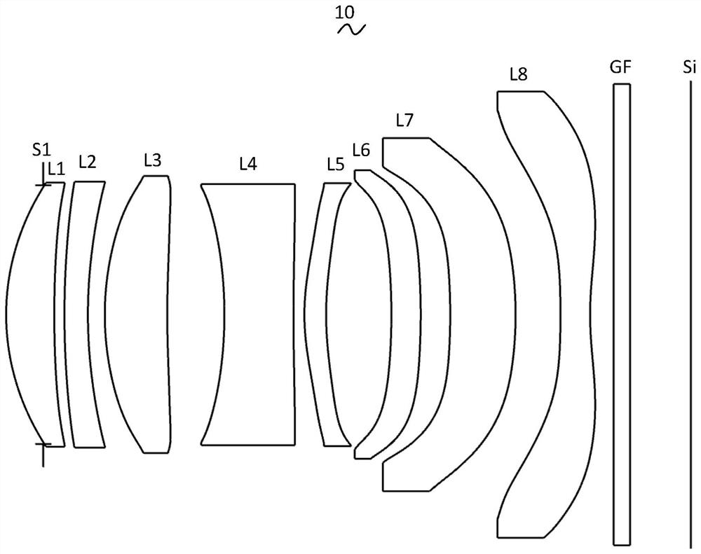
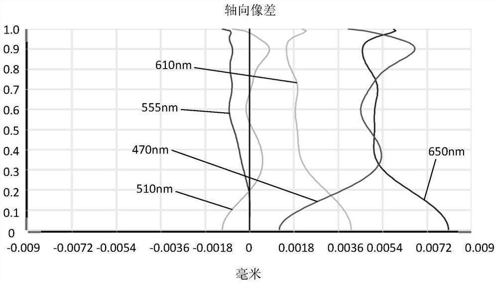
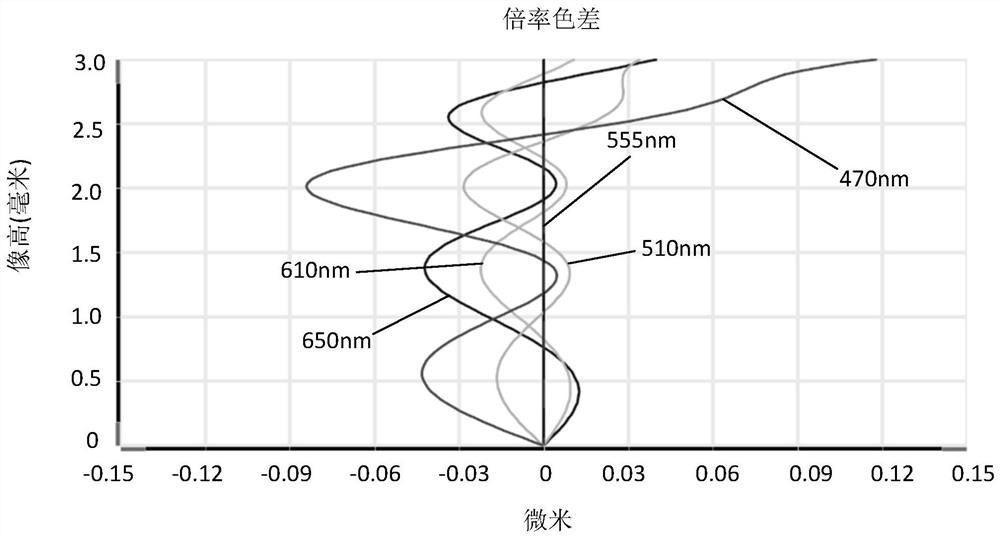
[0032] Referring to the accompanying drawings, the present invention provides an imaging optical lens 10. FIG. 1 shows the first embodiment of the present invention.
[0036] 0.95≤f / TTL; (1)
[0038] 0.25≤(R15+R16) / (R15-R16)≤0.90. (3)
[0043] In this embodiment, the object side surface of the first lens L1 is a convex surface at the paraxial position, and the image side surface is a concave surface at the paraxial position.
[0047] In this embodiment, the object side surface of the second lens L2 is a convex surface at the paraxial position, and the image side surface is a concave surface at the paraxial position.
[0050] In this embodiment, the object side surface of the third lens L3 is a convex surface at the paraxial position, and the image side surface is a concave surface at the paraxial position.
[0054] In this embodiment, the object side of the fourth lens L4 is concave at the paraxial position, and the image side is concave at the paraxial position.
[0058] In this...
no. 2 approach
[0154] FIG. 5 is a schematic structural diagram of an imaging optical lens 20 according to a second embodiment of the present invention. Sixth lens L6
[0155] Tables 5 and 6 show design data of the imaging optical lens 20 according to the second embodiment of the present invention.
[0157]
[0158]
[0159] Table 6 shows aspheric surface data of each lens in the imaging optical lens 20 according to the second embodiment of the present invention.
[0161]
[0164]
[0166]
[0168] As shown in Table 13, the second embodiment satisfies each conditional expression.
no. 3 approach
[0172] FIG. 9 is a schematic diagram showing the structure of the imaging optical lens 30 according to the third embodiment of the present invention.
[0173] Tables 9 and 10 show design data of the imaging optical lens 30 according to the third embodiment of the present invention.
[0175]
[0176]
[0177] Table 10 shows aspheric surface data of each lens in the imaging optical lens 30 according to the third embodiment of the present invention.
[0179]
[0180]
[0183]
[0185]
[0186]
[0188] The following Table 13 lists the numerical values corresponding to each conditional expression in this embodiment according to the above-mentioned conditional expression. Obviously, the actual
[0191]
PUM
 Abstract
Description
Claims
Application Information
 - R&D
- Intellectual Property
- Life Sciences
- Materials
- Tech Scout
- Unparalleled Data Quality
- Higher Quality Content
- 60% Fewer Hallucinations
Browse by: Latest US Patents, China's latest patents, Technical Efficacy Thesaurus, Application Domain, Technology Topic, Popular Technical Reports.
© 2025 PatSnap. All rights reserved.Legal|Privacy policy|Modern Slavery Act Transparency Statement|Sitemap|About US| Contact US: help@patsnap.com


