Microscopic imaging assembly, device and system adopting array type objective lens and imaging method

A technology of microscopic imaging and imaging methods, applied in microscopes, optical components, optics, etc., can solve the problems of limited observation area size and poor observation timeliness of microscopic systems, and achieve the effect of overcoming a large field of view

Active Publication Date: 2021-01-05
XI'AN INST OF OPTICS & FINE MECHANICS - CHINESE ACAD OF SCI
View PDF7 Cites 0 Cited by
  • Summary
  • Abstract
  • Description
  • Claims
  • Application Information

AI Technical Summary

Problems solved by technology

[0008] The purpose of the present invention is to solve the technical problems of poor observation timeliness and limited observation area size in existing microscopic systems, and to provide a microscopic imaging component, device, system and imaging method using an array objective lens

Method used


Image

  • Microscopic imaging assembly, device and system adopting array type objective lens and imaging method
  • Microscopic imaging assembly, device and system adopting array type objective lens and imaging method
  • Microscopic imaging assembly, device and system adopting array type objective lens and imaging method

Examples


Embodiment 1

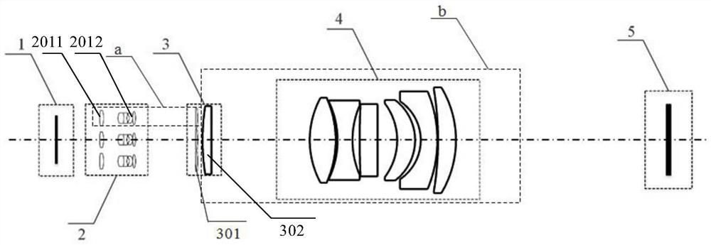
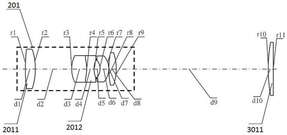
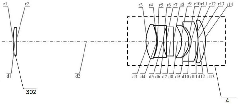
[0059] A microscopic imaging system using an arrayed objective lens, such as Figures 1 to 3 As shown, it includes an objective lens array 2 (array imaging objective lens), a field lens combination 3 (double field lens assembly), a secondary compensation magnification lens group 4 (near field image transmission mirror) and a detector arranged in sequence along the light transmission direction 6 (electronics focal plane detector, image sensor, commercial detector of 5-10 micron pixel resolving power); Described objective lens array 2 comprises 3 * 3 objective lens units 201 (that is 9 Near-field low-magnification objective lens units 201 with consistent parameters are arranged in a nine-square grid); each objective lens unit 201 includes a first objective lens 2011 and a primary magnification lens group 2012 arranged in sequence along the light transmission direction; the field lens combination 3 includes In the transmission direction, a first field lens array 301 and a second ...

Embodiment 2

[0074] The difference with embodiment 1 only lies in:

[0075] In step 2) of the imaging method, the control of the translation of the sample slide in the object plane 1 by the two-dimensional translation stage is replaced by the control of the imaging system to perform three translations in the plane perpendicular to the optical axis.

Embodiment 3

[0077] The difference with embodiment 1 only lies in:

[0078] Such as Figure 6 As shown, one detector 6 at the image plane 5 of the imaging system is replaced with 3×3 detectors 6 arranged coplanarly in an array and corresponding to 3×3 objective lens units 201 one-to-one. In imaging, Each detector can effectively overcome the image plane curvature (field curvature) effect caused by the large field of view hybrid optical axis imaging system through small adjustments of tilt and working distance, and further obtain high-resolution imaging results.


PUM


Abstract

The invention relates to a microscopic imaging assembly, device and system for realizing large-view-field staring imaging by using an array objective lens and an imaging method. The invention aims tosolve the technical problems of poor observation timeliness and limited size of an observation area of an existing microscopic system. On the basis of an existing compound microscopic system which isprovided with a primary phase surface and is imaged through a computer, a single objective lens is replaced with an objective lens array, a field lens combination is additionally arranged between theobjective lens array and a secondary compensation magnification lens set, the objective lens array and the secondary compensation magnification lens set are flattened through the field lens combination, the conversion from multiple optical axes to a single optical axis is achieved, and a sample glass slide and a microscope system perform limited times of relative translation during imaging, so that the objective lens array can completely cover all view fields of the sample glass slide during testing, exposure imaging is performed at an initial position and after each time of translation, and images obtained by multiple times of imaging are fused, so that a global image of the sample target area is obtained.

Description

technical field [0001] The invention relates to a microscopic imaging device, in particular to a microscopic imaging component, device, system and imaging method for realizing staring imaging with a large field of view by using an arrayed objective lens. Background technique [0002] It has been more than 400 years since humans first used optical lenses in the true sense to magnify objects (1590, originated in the Netherlands), and the first recognized microscope appeared at the end of the 17th century. As an indispensable optical instrument for human beings in many disciplines such as biology, chemistry, medicine and physics, microscopes continue to play an important role in scientific research and production. [0003] Divided from the form of composition, microscopes can be divided into single-lens systems, tube-lens microscope systems and compound microscope systems. [0004] The representative of the single-lens system is the Hooke microscope, which has a simple structu...

Claims


Application Information

Patent Timeline
Patent Type & Authority Applications(China)
IPC IPC(8): G02B21/02
CPCG02B21/02
Inventor 孙鑫白永林李然陈震石大莲王乐
Owner XI'AN INST OF OPTICS & FINE MECHANICS - CHINESE ACAD OF SCI
Why Eureka
Try Eureka