MEMS microphone chip, manufacturing method of chip module and electronic device

A manufacturing method and chip module technology, applied to electrical components, electrostatic transducer microphones, sensors, etc., can solve the problems of MEMS microphone sensitivity and signal-to-noise ratio reduction, reduce MEMS microphone sensitivity and signal-to-noise ratio, etc., and achieve good Effects of vibration, lower stiffness, and increased vibration effect

Inactive Publication Date: 2021-01-05
WEIFANG GOERTEK MICROELECTRONICS CO LTD
View PDF4 Cites 6 Cited by
  • Summary
  • Abstract
  • Description
  • Claims
  • Application Information

AI Technical Summary

Problems solved by technology

However, the sensitivity and signal-to-noise ratio of this MEMS microphone will decrease with the expansion of the diaphragm and back plate area. After the back pole and the diaphragm are powered on, the diaphragm will move towards the back pole. At this time, the diaphragm is in the It is easy to bond with the backplane during the vibration process, but in the exemplary technology, the diaphragm cannot vibrate well on the basis of ensuring that the diaphragm is not bonded to the backplane during the vibration process, which reduces the sensitivity and signal-to-noise of the MEMS microphone Compare

Method used


Image

  • MEMS microphone chip, manufacturing method of chip module and electronic device
  • MEMS microphone chip, manufacturing method of chip module and electronic device
  • MEMS microphone chip, manufacturing method of chip module and electronic device

Examples


Embodiment Construction

[0073] The following will clearly and completely describe the technical solutions in the embodiments of the present invention with reference to the accompanying drawings in the embodiments of the present invention. Obviously, the described embodiments are only part of the embodiments of the present invention, not all of them. Based on the embodiments of the present invention, all other embodiments obtained by persons of ordinary skill in the art without creative efforts fall within the protection scope of the present invention.

[0074] It should be noted that all directional indications (such as up, down, left, right, front, back...) in the embodiments of the present invention are only used to explain the relationship between the components in a certain posture (as shown in the accompanying drawings). Relative positional relationship, movement conditions, etc., if the specific posture changes, the directional indication will also change accordingly.

[0075] In addition, the ...


PUM


Abstract

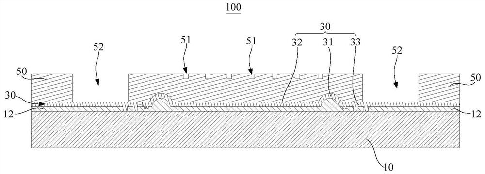
The invention discloses an MEMS microphone chip, a manufacturing method of a chip module, and an electronic device. The MEMS microphone chip comprises a substrate which is provided with a gap; and a back pole and a vibrating diaphragm. The vibrating diaphragm and the back pole are arranged on the same side of the substrate, an insulating area is arranged on the side, facing the vibrating diaphragm, of the back pole, the vibrating diaphragm and at least part of the back pole are arranged at intervals and form a vibrating gap, the vibrating diaphragm is provided with a protruding part bent towards the back pole, and the protruding part is located in the vibrating gap, and is movably abutted against the insulating area so as to limit the amplitude of the vibrating diaphragm. According to thetechnical scheme, on the basis that the vibrating diaphragm is not bonded with the back plate in the vibrating process, the vibrating diaphragm vibrates well, and the sensitivity and the signal-to-noise ratio of the MEMS microphone are improved.

Description

technical field [0001] The invention relates to the technical field of electroacoustic devices, in particular to a MEMS microphone chip, a manufacturing method of a chip module and electronic equipment. Background technique [0002] MEMS (Micro Electro Mechanic System, micro electromechanical system) microphone is a kind of electric energy sound transducer made by micromachining technology, which has the characteristics of small size, good frequency response characteristics, and low noise. With the miniaturization and thinning of electronic devices, MEMS microphones are more and more widely used in these devices. [0003] The MEMS microphone in the related art includes a silicon substrate and a plate capacitor composed of a diaphragm and a back plate, and the diaphragm is opposite to the back plate and separated by a certain distance. The diaphragm vibrates under the action of sound waves, causing the distance between the diaphragm and the back plate to change, resulting in...

Claims


Application Information

Patent Timeline
IPC IPC(8): H04R19/04H04R31/00
CPCH04R19/04H04R31/00H04R2201/003
Inventor 周宗燐邱冠勋卓彥萱
Owner WEIFANG GOERTEK MICROELECTRONICS CO LTD
Why Eureka
Try Eureka