An agricultural pollination drone with high pollination rate

A drone and pollination rate technology, applied in applications, aircraft parts, plant genetic improvement, etc., can solve problems such as poor pollination effect, achieve good pollination effect, improve success rate, and promote the effect of one-way flow

Active Publication Date: 2021-11-12
苏州渭塘文化产业发展有限公司
View PDF0 Cites 0 Cited by
  • Summary
  • Abstract
  • Description
  • Claims
  • Application Information

AI Technical Summary

Problems solved by technology

[0005] The purpose of the present invention is to solve the problem of poor pollination effect and provide an agricultural pollination drone with good pollination effect and high pollination rate

Method used


Image

  • An agricultural pollination drone with high pollination rate
  • An agricultural pollination drone with high pollination rate
  • An agricultural pollination drone with high pollination rate

Examples


Embodiment 1

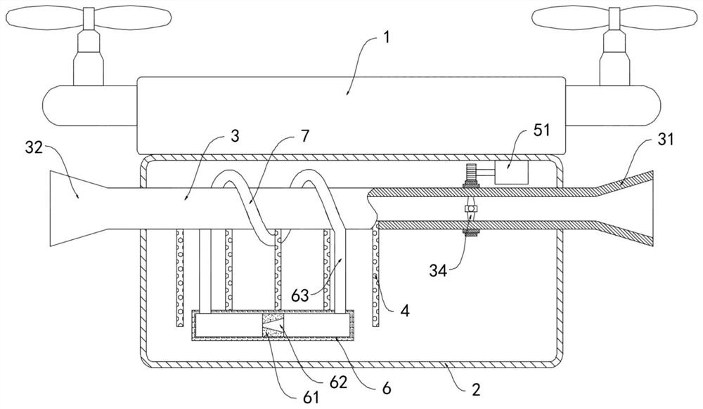
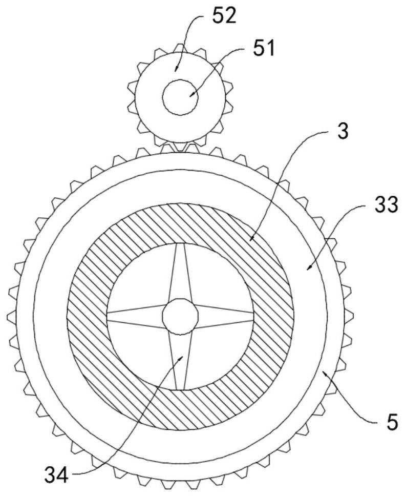
[0020] like Figure 1-2 As shown in a high agricultural pollination pollination UAV, includes a body 1, the lower surface of the body 1 of the box 2 is attached to pollen, pollen inner box 2 is fixed through the horizontal duct 3, one end of the duct 3 is provided air inlet 31, the other end is provided with an air outlet 32, inlet 31 and outlet 32 ​​showed a funnel shaped opening, the duct 3 is connected to the outer rotor permanent magnet ring 33, the inner top surface of the box 2 is provided with pollen for driving the permanent magnetic drive mechanism 33 rotates, to be noted that the drive mechanism comprises a toothed ring fixed coaxially sheathing the outer ring 33 of the permanent magnet 5, the inner top surface of the box 2 is attached to the pollen output shaft of the motor 51, the motor 51 a gear 52 is mounted, the gear 52 meshing with the toothed ring 5, the inner wall of the duct 3 is rotatably connected to the fan 34, the fan 34, wherein two opposing blades made of m...

Embodiment 2

[0025] like image 3 , The present embodiment is different from Example 1 in that: the duct 3 is provided with a plurality of turns embedded helical coil 8, 8 opposing helical coil wound in the vertical direction of the permanent magnet ring 33 in the direction sense lines, duct 3 top and bottom surfaces are fixedly connected to the plurality of positive discharge needle tip and do not contact 9, two pairs of n discharge needles 9 each electrically connected to both ends of the helical coil 8.

[0026] In the present embodiment, when the permanent magnet ring 33 is rotated, the cutting continuous helical coil 8 permanent magnet ring 33 generates magnetic field lines induced current, power to the discharge needles 9, the cumulative amount of charge on the discharge needles 9, the air discharge breakdown, 3 so that dirt particles inside the duct carrying the charge air, dust particles and the charge-carrying pollen contact adhesive sprayed out of the flower pollen adhered to more imp...


PUM


Abstract

The invention belongs to the technical field of agricultural unmanned aerial vehicles, and in particular relates to an agricultural pollination unmanned aerial vehicle with high pollination rate. One end of the air pipe is provided with an air inlet, and the other end is provided with an air outlet. Both the air inlet and the air outlet are arranged in a funnel-shaped opening. The outer rotation of the air pipe is connected with a permanent magnetic ring. The pollen box The inner top surface of the air duct is provided with a driving mechanism for driving the rotation of the permanent magnet ring. A fan is rotatably connected to the inner wall of the air duct, and the two opposite blades of the fan are made of magnetic materials and are connected with the permanent magnet ring. Different poles attract each other, and the side wall of the air duct is fixedly communicated with a plurality of equidistantly arranged suction pipes. In the present invention, the pollen is fully mixed with air and then sprayed out, the pollination effect is good, and the pollen is prevented from being directly agitated by the fan blade to cause damage, the temperature of the pollen is continuously reduced through the cooling tube, and the pollen activity is prevented from being affected by the temperature rise in the pollen box.

Description

Technical field [0001] The present invention belongs to the technical field of agricultural UAV, UAV particularly relates to one kind of agricultural pollinated pollinated rate. Background technique [0002] Pollination is a strong technical requirement, high precision, time-tight job Pollinating significantly affected by various factors, for pollination methods make high demands, the prior art will be used for pollination UAV crop pollination, pollination this way to solve the traditional style of human and mechanical labor intensity of pollination, influenced by environmental factors and other issues. [0003] The following problems when a conventional UAV pollination: 1, is directly rotated by the fan blows pollen discharge, uneven airflow blowing pollen, pollen and the process of movement, with the blade easily collide, resulting in some pollen damaged, the result is not ideal pollination; 2, long hours of work, due to heat, direct sunlight and pollen inside temperature rise ...

Claims


Application Information

Patent Timeline
Patent Type & Authority Patents(China)
IPC IPC(8): A01H1/02B64D1/18
CPCB64D1/18
Inventor 郑珏
Owner 苏州渭塘文化产业发展有限公司
Why Eureka
Try Eureka