
A biofilm waste gas treatment equipment

A technology for waste gas treatment equipment and biofilm, which is applied in air quality improvement, separation method, and dispersed particle separation, etc., can solve the problems of increasing the cost of the absorption packed tower, easy blockage of the lower packing, and poor absorption effect, and achieves less blockage. , The absorption is even and sufficient, the effect is good

Active Publication Date: 2022-07-19
青岛市金旭环境工程有限公司
View PDF11 Cites 0 Cited by
  • Summary
  • Abstract
  • Description
  • Claims
  • Application Information

AI Technical Summary

Problems solved by technology

The selection of the spray pump needs to be based on the characteristics of the spray, and its lift requirements are high. In order to ensure the pressure requirements of the upper sprinkler system, the lower sprinkler system is controlled by a pressure-stabilizing valve or a ball valve, which not only increases the cost of the absorption packing tower, but also increases the cost of the absorption tower. The spraying effect of the spraying system will be affected by the opening degree of the pressure stabilizing valve or ball valve
[0007] On the other hand, the spray liquid in contact with the vertically arranged lower packing has passed through the upper packing, the water contains more impurities, the lower packing is easy to clog, and the absorption effect is not good.

Method used


Image

  • A biofilm waste gas treatment equipment
  • A biofilm waste gas treatment equipment
  • A biofilm waste gas treatment equipment

Examples


Embodiment Construction

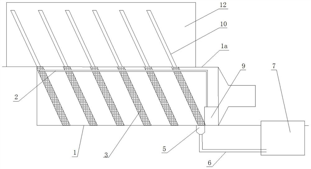
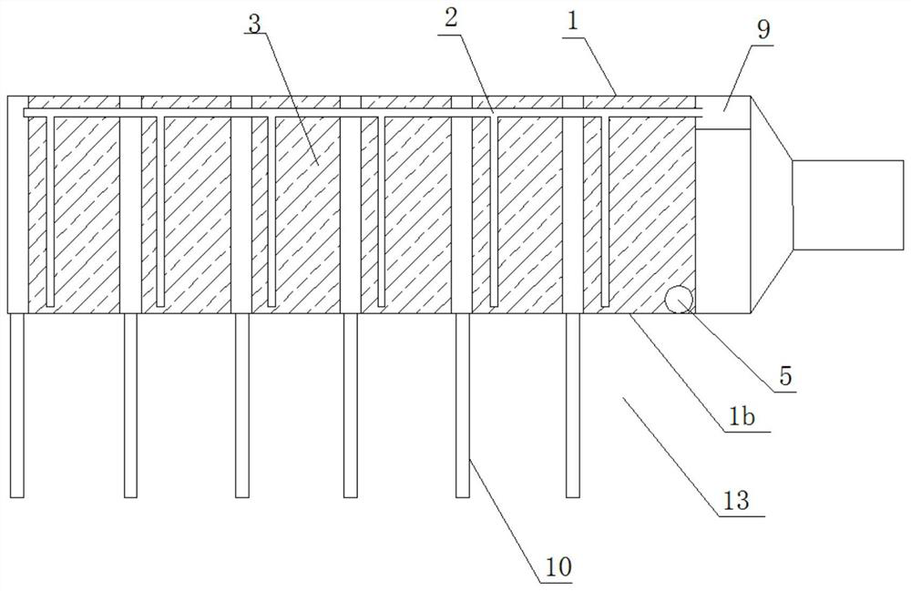
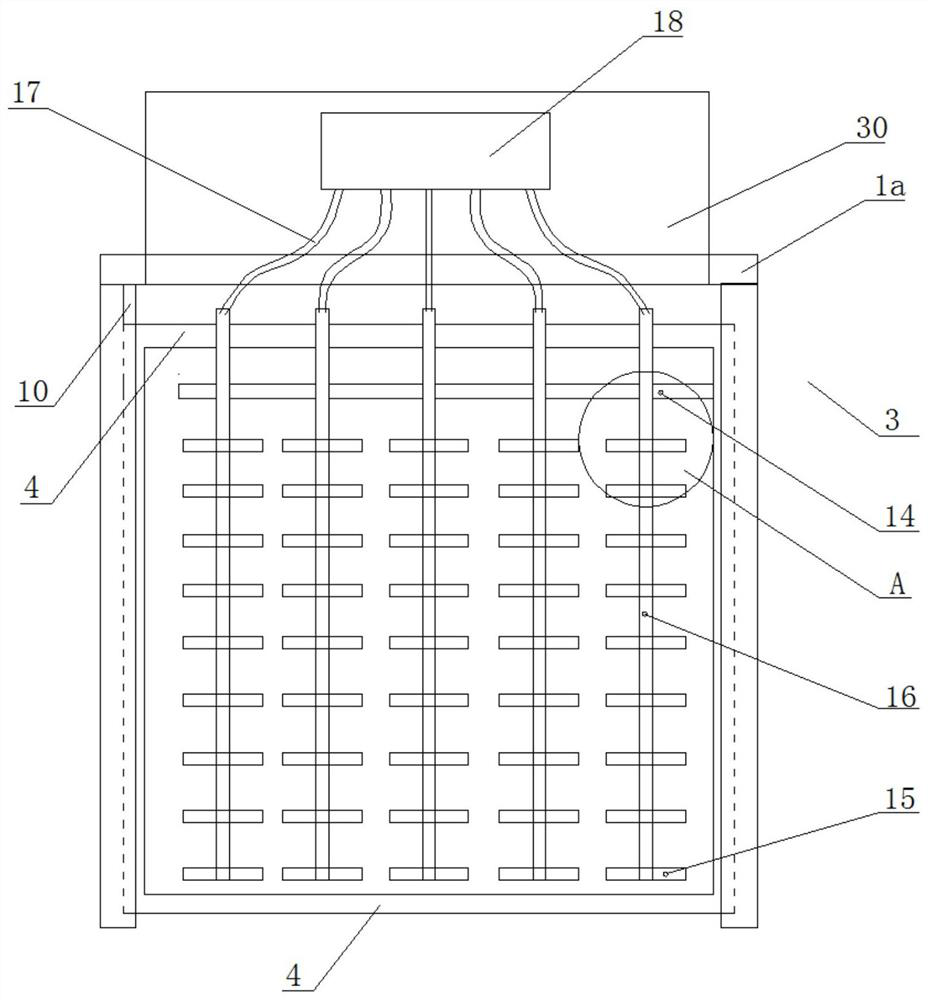
[0034] like figure 1 and figure 2 As shown, the biofilm waste gas treatment equipment of the present invention includes a box body 1, a waste gas channel arranged on the box body 1, a spray system 2 and a control device arranged on the upper part of the box body 1, and the box body 1 includes a side wall 1b, bottom plate and top cover 1a, a plurality of biofilm filler plates 3 are arranged in the box 1, preferably six biofilm filler plates 3 are arranged, and each biofilm filler plate 3 includes a frame 4 and is installed on the frame 4 The packing device 8, the exhaust gas channel is arranged laterally. The spray system 2 is connected to the control device, the control device is the electric control cabinet 9, the bottom of the rear end of the box 1 is provided with a sludge discharge port 5, the sludge discharge port 5 is connected to the sludge discharge pipe 6, and the sludge discharge pipe 6 is connected to the activated sludge Pool 7.

[0035] The exhaust gas channel...


PUM


Abstract

The invention relates to a biofilm waste gas treatment equipment, comprising a box body, a waste gas channel arranged on the box body, a spray system and a control device arranged on the upper part of the box body, and the box body comprises a side wall, a bottom plate and a top cover, A biofilm packing plate is arranged in the box, and the biofilm packing plate includes a frame and a packing device installed on the frame, and is characterized in that: the exhaust gas channel is arranged laterally. The waste gas channel of the present invention is arranged horizontally, and the flow direction of the spray liquid and the flow direction of the waste gas intersect vertically, and the absorption effect is better than that of the spray liquid from top to bottom and the waste gas from the bottom to the top, and the absorption is more uniform and sufficient; The flow direction of the filter is perpendicular to the direction of the spray liquid, and the efficiency of the contact absorption of the exhaust gas and the spray liquid is higher; such an arrangement structure can reduce the density of the filler, and can be set into a multi-layer drawable plate structure, so that the filler Maintenance and cleaning work is easier to carry out.

Description

technical field [0001] The invention relates to the technical field of waste gas treatment, in particular to equipment for purifying waste gas by utilizing biological membranes. Background technique [0002] Biological treatment is to use the life process of microorganisms to decompose and convert gaseous pollutants in exhaust gas into less or even harmless substances. A wide variety of microorganisms exist in nature, and almost all inorganic and organic pollutants can be transformed. Biological treatment does not require regeneration and other advanced treatment processes. Compared with other purification methods, it has the advantages of simple equipment, low energy consumption, safety and reliability, and no secondary pollution. [0003] Under suitable environmental conditions, microorganisms continuously absorb nutrients and carry out metabolic activities according to their own metabolic methods. Biological treatment of waste gas takes advantage of the fact that nutrie...

Claims


Application Information

Patent Timeline
Patent Type & Authority Patents(China)
IPC IPC(8): B01D53/84B01D53/14
CPCB01D53/84B01D53/14Y02A50/20
Inventor 栾明先张曦冉隋玉胜丁兆波
Owner 青岛市金旭环境工程有限公司
Learn More