
Cluster discharge control method of V2G direct-current charging pile

A technology for DC charging piles and discharge control, applied in charging stations, AC network circuits, electric vehicle charging technology, etc. energy loss etc.

Active Publication Date: 2021-01-08
国联智慧能源交通技术创新中心(苏州)有限公司 +1
View PDF5 Cites 5 Cited by
  • Summary
  • Abstract
  • Description
  • Claims
  • Application Information

AI Technical Summary

Problems solved by technology

However, for the discharge power of electric vehicles, the existing research is only by setting the corresponding discharge power in advance, and then once there is a discharge command, the electric vehicle will discharge according to the corresponding set power, and does not participate in real-time In the energy dispatching of the entire microgrid system, it is also impossible to give good feedback on the current power supply environment in real time, and it is impossible to give full play to the role played by the energy storage system in the microgrid
[0004] Insufficiency of the existing cluster control strategy: In the application environment of micro-grid peak shaving and valley filling, the energy management system collects demand data on the high-voltage side of the distribution network
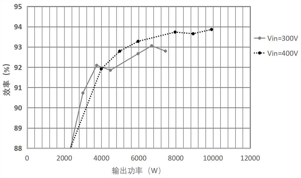
Since the output power P issued by the energy management system to the V2G charging pile out There is a high probability that it will not fall in the optimal power conversion range of the AC-DC hybrid conversion module [P min ,P max ], leading to low energy conversion efficiency of the AC-DC hybrid conversion module, resulting in loss of electric energy and reducing the benefits of electric vehicle users

Method used

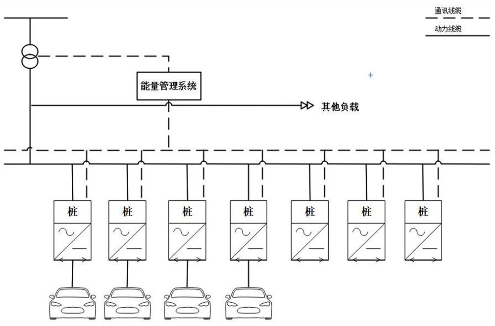

Image

  • Cluster discharge control method of V2G direct-current charging pile
  • Cluster discharge control method of V2G direct-current charging pile
  • Cluster discharge control method of V2G direct-current charging pile

Examples


Embodiment Construction

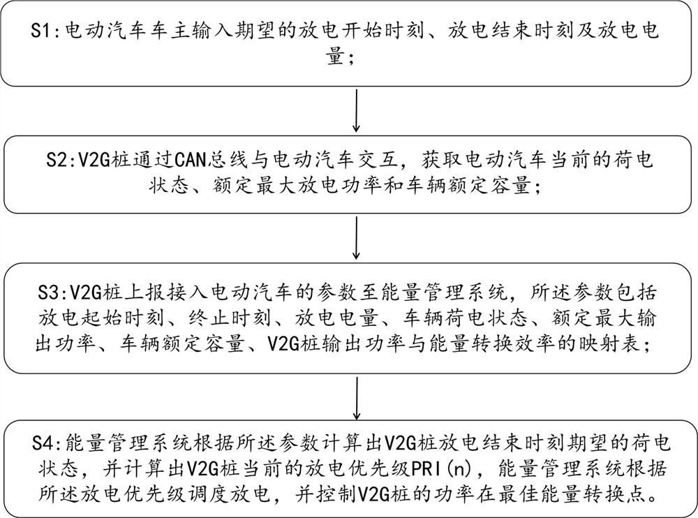
[0032] The present invention provides a cluster discharge control method for V2G DC charging piles, the flow chart of which is as follows figure 1 Shown, technical scheme of the present invention comprises the following steps:

[0033] Step S1: In order to facilitate the user to discharge the idle electric vehicle during the peak time, supply power to the grid and sell electricity, and improve the battery utilization rate, the user can input the expected discharge start time, discharge end time and discharge power of the electric vehicle;

[0034] Step S2: The V2G charging pile interacts with the electric vehicle through the CAN bus to obtain the current state of charge of the electric vehicle, the rated maximum discharge power and the rated capacity of the vehicle;

[0035]Step S3: The V2G charging pile reports the parameters of the electric vehicle connected to the energy management system. The parameters include the discharge start time, end time, discharge power, vehicle s...


PUM


Abstract

A cluster discharge control method of a V2G direct current charging pile relates to the field of electric vehicle and power grid interaction, and comprises the following steps: after an electric vehicle is connected to the V2G charging pile, a vehicle owner inputs expected discharge start time, end time and discharge electric quantity; the V2G charging pile interacts with the vehicle through a CANbus to obtain current parameters of the vehicle; the V2G charging pile reports the parameters of the accessed vehicle and a mapping table of the output power and the energy conversion efficiency of the V2G charging pile to an energy management system; and the energy management system calculates the discharge priority of the current vehicle, preferentially schedules the vehicle with the high priority to discharge at any time, and controls the power of the V2G charging pile to be at the optimal energy conversion point. Therefore, the utilization rate of the energy of an energy storage battery of the electric vehicle can be improved, the heat generated by an AC-DC hybrid conversion module can be reduced, and the aging speed of the AC-DC hybrid conversion module can be reduced.

Description

technical field [0001] The invention relates to the field of interaction between an electric vehicle and a power grid, in particular to a cluster discharge control method of a V2G DC charging pile. Background technique [0002] Electric vehicles are a type of new energy vehicles, which use batteries as energy, and convert electrical energy into mechanical energy through controllers, motors and other components. In the next 15 years, the production and sales of pure electric and plug-in hybrid vehicles will account for a considerable proportion of the total production and sales of vehicles, and the proportion of the total number of vehicles will increase rapidly year by year. [0003] With the development of the smart grid, when the grid load is high, the electric vehicle energy storage battery feeds power to the grid; when the grid load is low, it is used to store excess power generation in the grid to avoid waste. In this way, electric vehicles can buy electricity from the...

Claims


Application Information

Patent Timeline
IPC IPC(8): B60L55/00B60L53/60B60L53/66B60L53/31B60L53/64H02J3/32
CPCB60L53/31B60L53/60B60L53/64B60L53/66B60L55/00H02J3/008H02J3/322Y02T10/70Y02T10/7072Y02T10/72Y02T90/12Y02T90/16
Inventor 贾俊国彭晓峰王明才史剑冯中魁周凌霄李悦
Owner 国联智慧能源交通技术创新中心(苏州)有限公司
Learn More