Ceiling board combination structure

A combined structure and ceiling technology, which is applied in the direction of building components, building structures, building insulation materials, etc., can solve the problems of failing to meet the requirements of the purification level, the installation of high-efficiency filters in the middle of the ceiling board, and the inconvenience of maintenance and replacement. To achieve the effect of ensuring high-level cleanliness, avoiding instability, and simple and effective maintenance

Inactive Publication Date: 2021-01-08
LUYIYA IND DEV SHENZHEN CITY
View PDF18 Cites 2 Cited by
  • Summary
  • Abstract
  • Description
  • Claims
  • Application Information

AI Technical Summary

Problems solved by technology

[0002] In the current technology, some laboratory instrument processing and manufacturing industries have high requirements and controls on the air cleanliness of production sites and production equipment. Therefore, the air cleanliness in production sites and experimental sites requires strict management and control. , In the field of extremely high purification level, it is necessary to carry out the secondary ceiling installation of the ceiling keel. The cleanliness level is controlled by the high-efficiency filter, the air pressure difference and the air pressure flow direction, and the concentration of suspended particles in the air is controlled to achieve the design requirements of the product. However, the existing ceiling installations rarely use ceiling keel ceiling installations, resulting in high-efficiency filters that can only be installed in the middle of the ceiling board, which cannot meet the requirements of the field with extremely high purification levels, resulting in reduced or poor product quality. At the same time, the existing ceiling The device still has the problems of cumbersome installation, high installation cost, and inconvenient maintenance and replacement. At the same time, the blind plate of the existing ceiling device has the problems of low structural strength and low flatness when the two blind plates are connected.

Method used


Image

  • Ceiling board combination structure
  • Ceiling board combination structure
  • Ceiling board combination structure

Examples


Embodiment Construction

[0038] The following will clearly and completely describe the technical solutions in the embodiments of the present invention with reference to the accompanying drawings in the embodiments of the present invention. Obviously, the described embodiments are only some, not all, embodiments of the present invention. Based on the embodiments of the present invention, all other embodiments obtained by those skilled in the art without creative efforts fall within the protection scope of the present invention.

[0039] In describing the present invention, it should be understood that the terms "center", "longitudinal", "transverse", "length", "width", "thickness", "upper", "lower", "front", " Orientation or position indicated by "back", "left", "right", "vertical", "horizontal", "top", "bottom", "inner", "outer", "clockwise", "counterclockwise", etc. The relationship is based on the orientation or positional relationship shown in the drawings, and is only for the convenience of descri...


PUM


Abstract

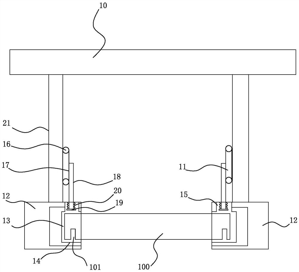
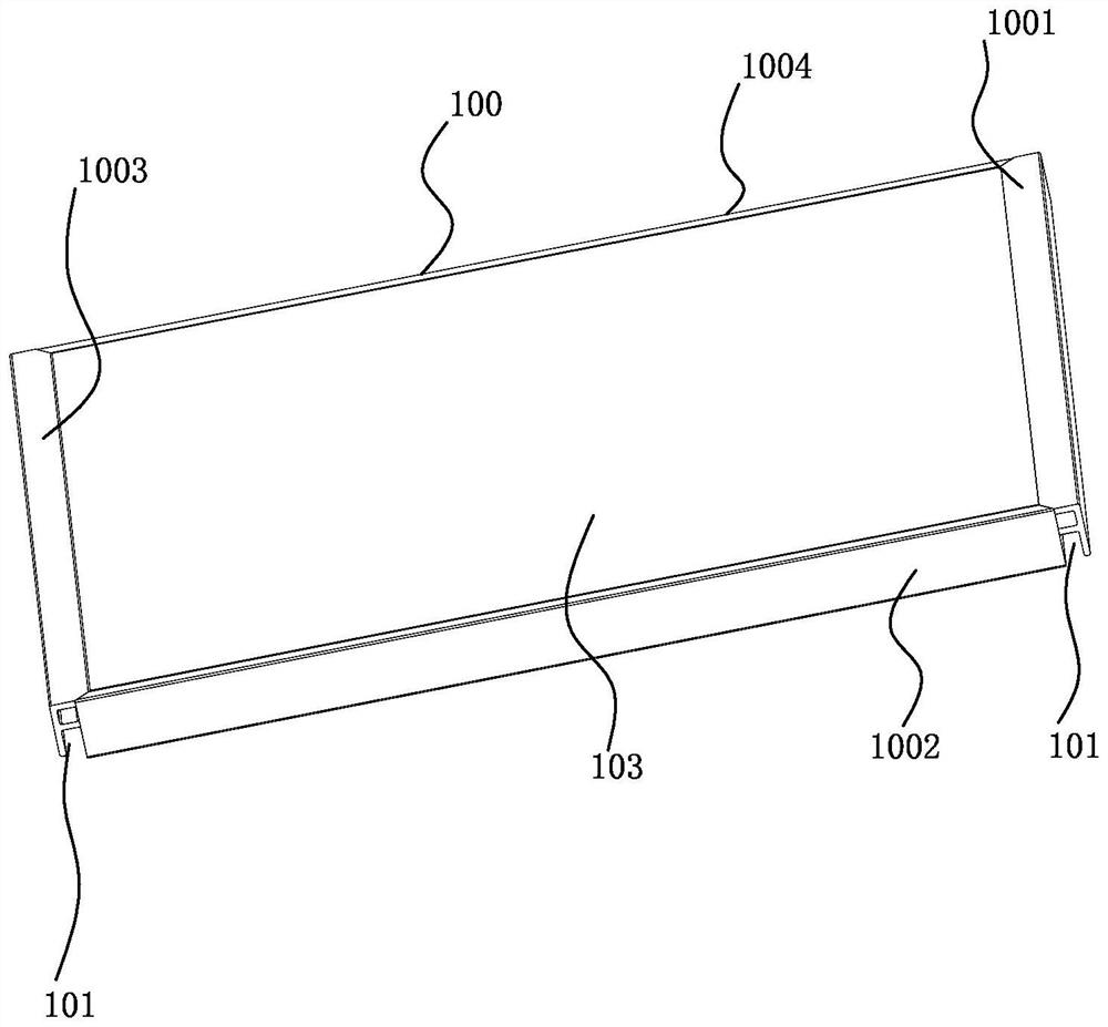
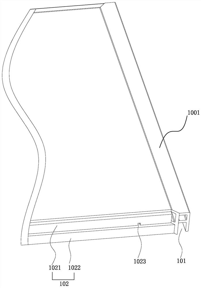
The invention discloses a ceiling board combination structure. The ceiling board combination structure comprises a keel frame, an adjusting assembly connected with the keel frame, a connector structure installed on the keel frame and ceiling boards installed on the connector structure; the connector structure is provided with installation grooves, the ceiling boards are installed in the installation grooves, sealing strips are installed in the installation grooves, installation holes are formed in the upper ends of the installation grooves, and the installation holes are connected with the adjusting assembly; and the adjusting assembly comprises a belt transmission mechanism, a lifting rod connected with a transmission belt of the belt transmission mechanism and pressing pieces installed at the lower end of the lifting rod. The ceiling boards are connected with the installation grooves in a sealed mode to achieve a good sealing effect, the ceiling boards can be prevented from being pressed to deform through the extrusion mode of the pressing pieces, the ceiling boards are connected through the assembly positions of the ceiling boards, stability is improved, instability of cleanliness of a dust-free room is effectively avoided, the structure is simple, light and convenient, strength is high, the cost is low, and maintenance is simple and effective.

Description

technical field [0001] The invention relates to the field of ceiling keel suspended ceiling structures, in particular to a composite structure of ceiling panels. Background technique [0002] In the current technology, some laboratory instrument processing and manufacturing industries have high requirements and controls on the air cleanliness of production sites and production equipment. Therefore, the air cleanliness in production sites and experimental sites requires strict management and control. , In the field of extremely high purification level, it is necessary to carry out the secondary ceiling installation of the ceiling keel. The cleanliness level is controlled by the high-efficiency filter, the air pressure difference and the air pressure flow direction, and the concentration of suspended particles in the air is controlled to achieve the design requirements of the product. However, the existing ceiling installations rarely use ceiling keel ceiling installations, re...

Claims


Application Information

Patent Timeline
Patent Type & Authority Applications(China)
IPC IPC(8): E04B9/00E04B9/04E04B9/06E04B1/66
CPCE04B1/66E04B9/00E04B9/04E04B9/06
Inventor 王佳佳夏宝王国帆王鹏刘宝李辉田新张峰张蓓莉季明官张柒季洁
Owner LUYIYA IND DEV SHENZHEN CITY
Why Eureka
Try Eureka