A high-speed rail fan assembly structure

An assembly structure and fan technology, applied in the direction of mechanical equipment, machine/engine, liquid fuel engine, etc., can solve the problems of impeller vibration, high-speed rail motor noise, etc., and achieve the possibility of reducing working noise, reducing noise, and reducing vibration Effect

Active Publication Date: 2022-04-15
上海新联金属新材料有限公司
View PDF5 Cites 0 Cited by
  • Summary
  • Abstract
  • Description
  • Claims
  • Application Information

AI Technical Summary

Problems solved by technology

When the motor drives the impeller to rotate, because the impeller rotates at a relatively fast speed, the impeller will vibrate during rotation, which will cause the high-speed rail motor to make a lot of noise in the working state
[0004] In view of the above-mentioned related technologies, the inventor believes that when the motor drives the impeller to rotate, because the impeller rotates at a relatively fast speed, the impeller will vibrate during rotation, resulting in relatively loud noise of the high-speed rail motor in the working state

Method used


Image

  • A high-speed rail fan assembly structure
  • A high-speed rail fan assembly structure
  • A high-speed rail fan assembly structure

Examples


Embodiment Construction

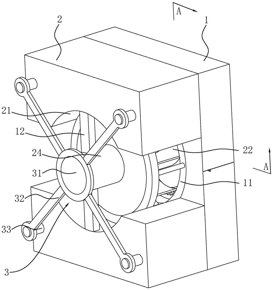
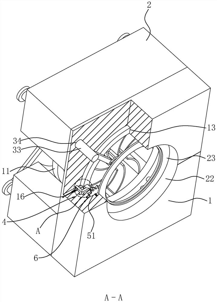
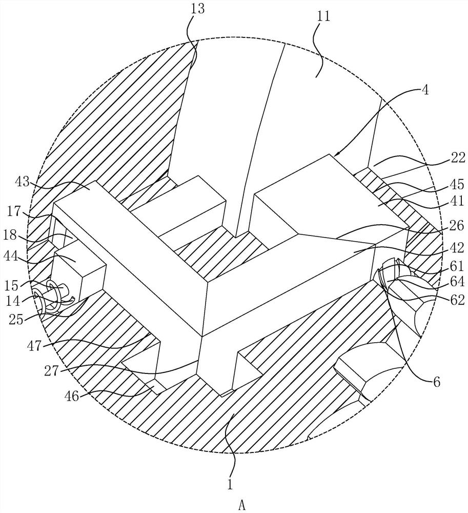
[0032] The following is attached Figure 1-4 The application is described in further detail.

[0033] The embodiment of the present application discloses a high-speed rail fan assembly structure. refer to figure 1 and figure 2 , the assembly structure includes an assembly plate 1 and two support frames 2 fixed on one side of the assembly plate 1 . The assembly plate 1 is composed of two high-speed rail fan accessories, and the two high-speed rail fan accessories are fixedly connected to each other. Arc-shaped grooves 21 for accommodating fans 11 are provided on opposite inner sides of the two supporting frames 2 . By fixing the fan 11 in the two arc-shaped grooves 21, it is convenient to limit the position of the fan 11 and reduce the possibility of the fan 11 being displaced in a working state. The inner peripheral surfaces of the two arc-shaped grooves 21 are respectively fixed with support rods 12 which are oppositely arranged and are respectively used to abut against...


PUM


Abstract

This application relates to a high-speed rail fan assembly structure, which includes an assembly plate and two support frames fixed on one side of the assembly plate; the side of the assembly plate close to the fan is provided with an air outlet hole; A fixed frame for pressing the fan motor to the side close to the assembly plate is detachably installed; the fixed frame includes a pressure plate for abutting against the side of the fan motor away from the fan, and four four-pieces fixed to the outer peripheral surface of the pressure plate along the circumferential direction of the pressure plate. A connecting rod; each connecting rod is fixed with a fixed shaft at the end far away from the pressure plate; four connecting grooves are opened on the side of the mounting plate close to the pressure plate, and each fixed shaft runs through the support frame and passes through the connecting groove along the axial direction of the pressure plate. The assembly plate is slidingly connected; the side of the assembly plate close to the support frame is provided with an annular groove for accommodating the fan; two sets of connection mechanisms for fixed connection with the outer peripheral surface of the fan are arranged in the annular groove. The application has the effect of reducing the noise when the high-speed rail fan is working.

Description

technical field [0001] The present application relates to the field of high-speed rail fan accessories, in particular to an assembly structure of a high-speed rail fan. Background technique [0002] At present, the high-speed rail fan is a kind of machine that relies on the input of mechanical energy to increase the gas pressure and discharge the gas to the outside. According to the principle of converting kinetic energy into potential energy, the high-speed rail fan uses a high-speed rotating impeller to accelerate the gas and convert kinetic energy into potential energy. [0003] For the prior art, please refer to the Chinese invention patent application with the publication number CN107642491A, which discloses a ternary fluidized centrifugal fan for cooling motor vehicles and high-speed rail traction transformers, including an impeller, a motor, and a motor mounting plate for installing the motor. The impeller includes a front Disc body, rear disc body, wheel hub and sev...

Claims


Application Information

Patent Timeline
Patent Type & Authority Patents(China)
IPC IPC(8): F04D29/62F04D29/66H01F27/08
CPCF04D29/626F04D29/668H01F27/085
Inventor 张维良向国强
Owner 上海新联金属新材料有限公司
Why Eureka
Try Eureka