Dust collection motor with high torque density

A dust-absorbing motor and high-torque technology, applied in the direction of electromechanical devices, electrical components, mechanical equipment, etc., can solve problems such as vibration and wind wheel noise, and achieve the effects of improving connection strength, reducing noise, and reducing possibility

Active Publication Date: 2020-10-02
常州永沛机电技术有限公司
View PDF6 Cites 0 Cited by
  • Summary
  • Abstract
  • Description
  • Claims
  • Application Information

AI Technical Summary

Problems solved by technology

In the dust-absorbing motor device mentioned above, the motor bracket fixes the wind wheel by pressing the motor to the side close to the motor, but there is no mechanism for fixed connection between the wind wheel and the machine base, which causes the wind wheel to rotate due to lack of The fixing mechanism will vibrate, so that the wind wheel will generate noise when it is working
[0004] For the above-mentioned related technologies, the inventor believes that there is a defect that the wind wheel generates noise when it is working

Method used


Image

  • Dust collection motor with high torque density
  • Dust collection motor with high torque density
  • Dust collection motor with high torque density

Examples


Embodiment Construction

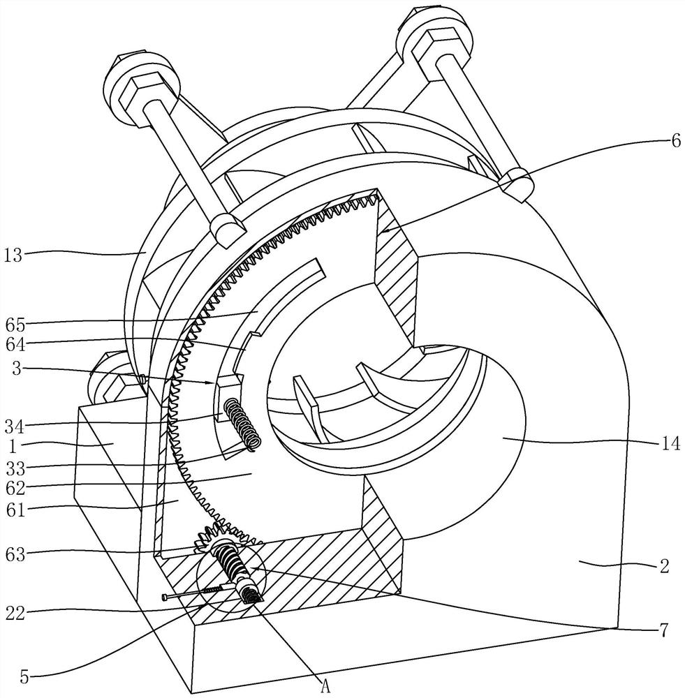
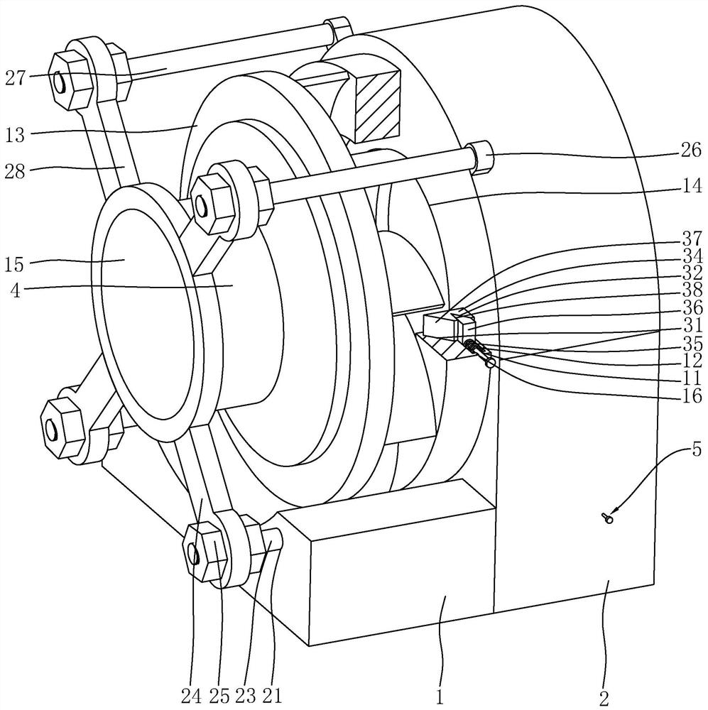
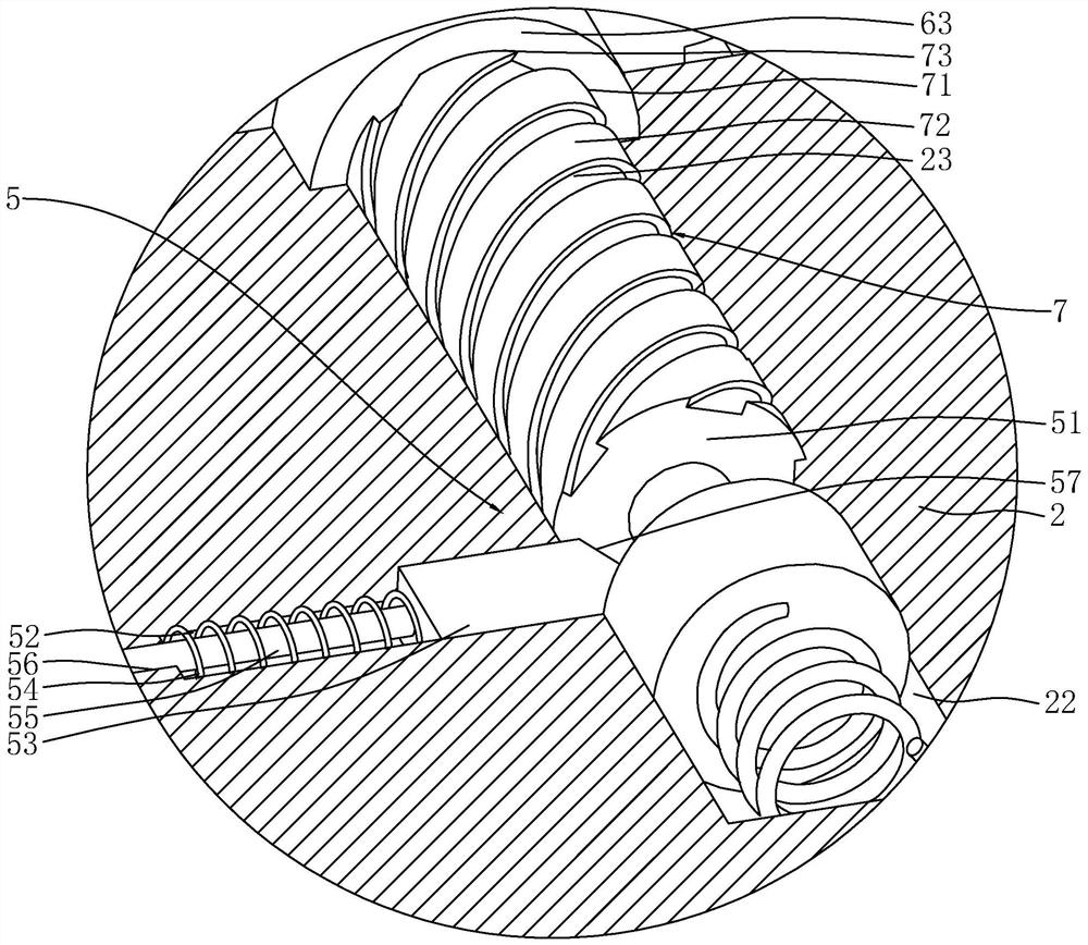
[0031] The following is attached Figure 1-3 The application is described in further detail.

[0032] The embodiment of the present application discloses a dust collection motor 4 with high torque density. refer to figure 1 , figure 2The vacuum motor 4 includes a base 1 , a frame 2 fixed on one side of the base 1 , and a wind wheel 13 detachably mounted on the side of the frame 2 close to the base 1 . A circular through hole 14 is opened on the side of the frame 2 close to the base 1 . Two sets of fixing mechanisms 3 for fixedly connecting the machine base 2 and the wind wheel 13 are arranged between the wind wheel 13 and the machine base 2 . The base 1 is provided with two first circular grooves 21 on the side away from the base 2, and the side of the base 2 close to the base 1 is provided with two second circular grooves 22 respectively communicating with the first circular grooves 21; In the first circular groove 21, a first connecting shaft 23 is provided to slide al...


PUM


Abstract

The invention relates to a dust collection motor with high torque density. The dust collection motor comprises a base, an engine base and a wind wheel; a circular through hole is formed in one side ofthe engine base close to the base; two sets of fixed mechanisms are arranged between the wind wheel and the engine base; two first circular grooves are formed in the side, away from the engine base,of the base; two second circular grooves are formed in the side, close to the base, of the engine base; first connecting shafts are slidably arranged in the two first circular grooves in the width direction of the base correspondingly; the bottom end of each first connecting shaft is provided with a brake assembly used for fixing the first connecting shaft; a driving assembly for driving the windwheel to rotate is arranged on the side, away from the engine base, of the wind wheel; each fixed mechanism comprises a first inserting groove formed in the side, close to the engine base, of the windwheel, a mounting groove formed in the side, close to the base, of the engine base, a first spring fixed to the side, away from the base, of the mounting groove, and a first inserting piece fixed tothe end, close to the base, of the first spring and used for being inserted into the first inserting groove. The possibility that noise is generated when the wind wheel works can be reduced.

Description

technical field [0001] The present application relates to the field of dust collection motors, in particular to a dust collection motor with high torque density. Background technique [0002] At present, the working principle of the vacuum cleaner is to use the motor to drive the blades to rotate at a high speed, generate negative air pressure in the sealed housing, and absorb dust. [0003] For the prior art, please refer to the Chinese utility model patent whose authorized announcement number is CN207041477U, which discloses a dust-absorbing motor device, including a dust-absorbing motor, a wind wheel, a turbine housing, and a motor bracket. The wind wheel is fixed to the rotor of the dust-absorbing motor On the top, the vacuum motor is fixed on the turbine air casing through the motor bracket. In the dust-absorbing motor device mentioned above, the motor bracket fixes the wind wheel by pressing the motor to the side close to the motor, but there is no mechanism for fixed...

Claims


Application Information

Patent Timeline
Patent Type & Authority Applications(China)
IPC IPC(8): A47L9/22F04D29/62F04D29/68H02K5/24H02K7/14
CPCA47L9/22F04D29/626F04D29/681H02K5/24H02K7/14
Inventor 聂敬礼聂敬忠刘磊
Owner 常州永沛机电技术有限公司
Why Eureka
Try Eureka