
Large-field-of-view survey telescope wavefront curvature sensing method, device and equipment, and medium

A wavefront curvature and sensing method technology, applied in the field of telescopes, can solve problems such as non-uniform illumination of pupils, inability to effectively target sky survey telescopes, and influence of phase recovery accuracy, so as to achieve accurate results, improve observation accuracy, and reduce correction time Effect

Active Publication Date: 2021-01-08
CHANGCHUN INST OF OPTICS FINE MECHANICS & PHYSICS CHINESE ACAD OF SCI
View PDF9 Cites 2 Cited by
  • Summary
  • Abstract
  • Description
  • Claims
  • Application Information

AI Technical Summary

Problems solved by technology

However, for large field of view sky survey systems, the single aberration range of the phase difference technology is less than one wavelength, which makes it unable to effectively target the edge field of view with large aberrations of the survey telescope; at the same time, the skylight background and vignetting caused Non-uniform illumination of the pupil will also affect the accuracy of phase recovery
Therefore, there are still many limiting factors for the application of phase difference technology in the wavefront sensing system of active optical telescopes for sky surveys

Method used

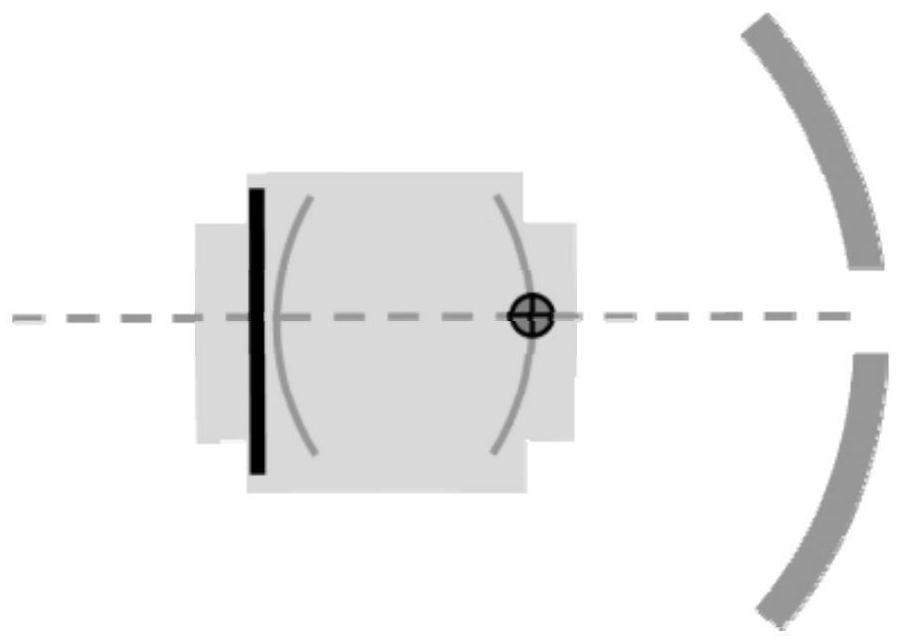
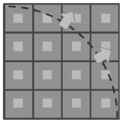

Image

  • Large-field-of-view survey telescope wavefront curvature sensing method, device and equipment, and medium
  • Large-field-of-view survey telescope wavefront curvature sensing method, device and equipment, and medium
  • Large-field-of-view survey telescope wavefront curvature sensing method, device and equipment, and medium

Examples


Embodiment Construction

[0037] The following will clearly and completely describe the technical solutions in the embodiments of the present invention with reference to the accompanying drawings in the embodiments of the present invention. Obviously, the described embodiments are only some, not all, embodiments of the present invention. Based on the embodiments of the present invention, all other embodiments obtained by persons of ordinary skill in the art without making creative efforts belong to the protection scope of the present invention.

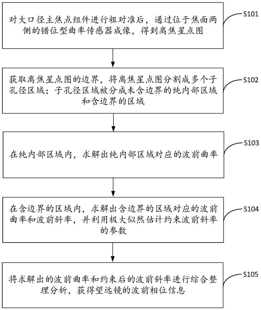
[0038] The invention provides a method for sensing wavefront curvature of a large-field survey telescope, such as figure 1 shown, including the following steps:

[0039] S101. After roughly aligning the large-aperture main focus component, image through the misplaced curvature sensors located on both sides of the focal plane to obtain an out-of-focus star point map;

[0040] It should be noted that increasing the caliber of the wide-field survey telescope can...


PUM


Abstract

The invention discloses a large-field-of-view survey telescope wavefront curvature sensing method, device and equipment, and a medium. The large-field-of-view survey telescope wavefront curvature sensing method comprises the steps of: carrying out coarse alignment on a large-caliber main focus assembly, and carrying out imaging through using staggered curvature sensors located at two sides of a focal plane to obtain an out-of-focus star point graph; acquiring the boundary of the out-of-focus star point graph, and segmenting the out-of-focus star point graph into a plurality of sub-aperture regions, wherein each sub-aperture region is divided into a pure internal region without a boundary and a boundary-containing region; in the pure internal regions, solving wavefront curvatures corresponding to the pure internal regions; in the boundary-containing regions, solving the wavefront curvatures and the wavefront slopes corresponding to the boundary-containing regions, and estimating the parameters of the constrained wavefront slopes by using the maximum likelihood; and carrying out comprehensive arrangement and analysis on the solved wavefront curvatures and the constrained wavefront slopes to obtain wavefront phase information of the telescope. In this way, the finally solved wavefront sensing result is more accurate, the correction time is shortened, and the correction precision is improved.

Description

technical field [0001] The invention relates to the technical field of telescopes, in particular to a wavefront curvature sensing method, device, equipment and medium of a large-field survey telescope. Background technique [0002] The increase of the telescope caliber can not only effectively improve the resolution ability of nearby targets, but also improve the light-gathering ability of the telescope with the square law, which can effectively improve the signal-to-noise ratio of faint target imaging, expand the limit detection capability, and finally realize the detection of the farther-reaching universe. exploration. Therefore, large-aperture and large-field telescopes are the key to verifying the latest theories of cosmology and increasing the academic discourse power in the fields of time-domain astronomy in the future. [0003] The large aperture and large field of view telescope has developed rapidly in the past two decades. In order to obtain higher sky survey effi...

Claims


Application Information

Patent Timeline
Patent Type & Authority Applications(China)
IPC IPC(8): G01J9/00G02B23/00G02B27/00
CPCG01J9/00G01J2009/002G02B23/00G02B27/0025
Inventor 安其昌吴小霞林旭东王建立陈涛李洪文
Owner CHANGCHUN INST OF OPTICS FINE MECHANICS & PHYSICS CHINESE ACAD OF SCI
Learn More