Stable-temperature airflow heating device for low-speed direct-current wind tunnel simulation experiment and wind tunnel

A technology of airflow heating and simulation experiments, which is applied to measuring devices, using electric methods for temperature control, temperature control, etc. The effect of improving temperature uniformity

Pending Publication Date: 2021-01-08
NORTHWESTERN POLYTECHNICAL UNIV
View PDF5 Cites 1 Cited by
  • Summary
  • Abstract
  • Description
  • Claims
  • Application Information

AI Technical Summary

Problems solved by technology

[0004] In view of the deficiencies in the prior art, the purpose of the present invention is to provide a low-speed straight-flow wind tunnel simulation experiment of a steady-temperature airflow heating device and a wind tunnel, t

Method used


Image

  • Stable-temperature airflow heating device for low-speed direct-current wind tunnel simulation experiment and wind tunnel
  • Stable-temperature airflow heating device for low-speed direct-current wind tunnel simulation experiment and wind tunnel
  • Stable-temperature airflow heating device for low-speed direct-current wind tunnel simulation experiment and wind tunnel

Examples


Embodiment 1

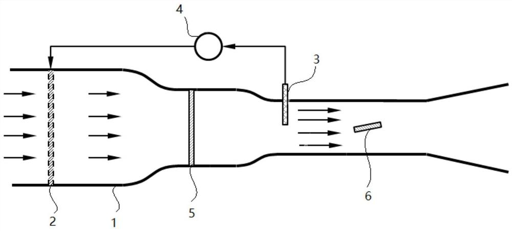
[0029] Such as figure 1 Shown is the schematic diagram of the present invention, the airflow is sucked into the wind tunnel by the fan, the airflow is heated, and then passes through the turbulence generator to generate the flow field with the required turbulence intensity. The airflow enters the test section after passing through the constriction section to form the flow field required for the test.

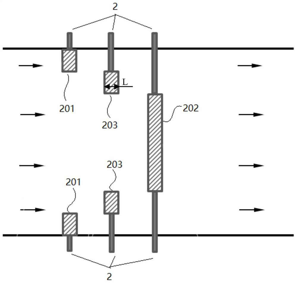
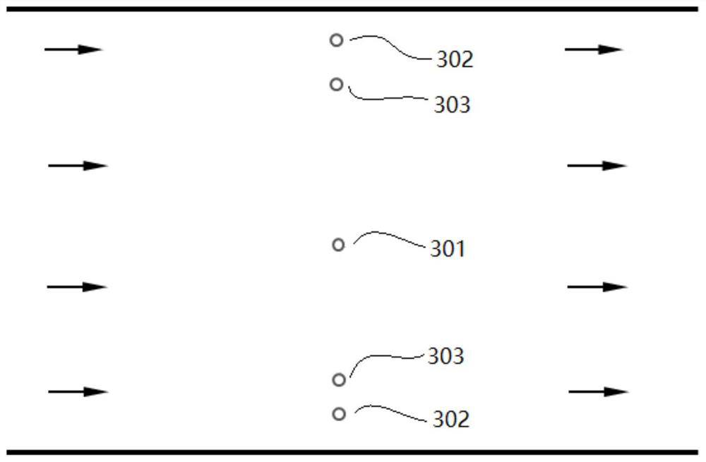
[0030] In order to make the airflow temperature distribution on the cross-section of the wind tunnel test section more uniform or to change the airflow temperature distribution on the cross-section of the wind tunnel test section, this embodiment proposes a low-speed direct current wind tunnel simulation experiment with a steady-temperature airflow heating device, including Airflow heating unit 2, temperature monitoring unit 3 and control unit 4. Generally, a temperature monitoring unit 3 is placed upstream of the wind tunnel test section, and the temperature monitoring unit 3 ...

Embodiment 2

[0040] This embodiment discloses a low-speed straight-line wind tunnel, which includes a wind tunnel body, an airflow heating unit, a temperature monitoring unit and a turbulence generator 5 arranged in the wind tunnel body. Wherein, the wind tunnel body 1 is in the shape of a common wind tunnel in the existing market, and the airflow heating unit and the temperature monitoring unit are respectively the airflow heating unit 2 and the temperature monitoring unit 3 described in Embodiment 1.

[0041] Such as figure 1 As shown, in this embodiment, the airflow heating unit 2 is arranged upstream of the turbulent flow generator 5 ; the temperature monitoring unit 3 is arranged downstream of the turbulent flow generator 5 and in front of the test piece 6 .

[0042] By using the wind tunnel of this embodiment, a flow field with uniform airflow temperature or a flow field with different airflow temperatures at different positions on the same cross section can be obtained.

[0043] Wh...


PUM


Abstract

The invention discloses a stable-temperature airflow heating device for a low-speed direct-current wind tunnel simulation experiment and a wind tunnel. The device comprises airflow heating units, a temperature monitoring unit and a control unit, at least two groups of airflow heating units are symmetrically arranged along the axis of the wind tunnel; each airflow heating unit group comprises at least two heaters, the heaters in each airflow heating unit group are sequentially distributed in the airflow direction in the wind tunnel, and the heaters are sequentially distributed from the positionnear the inner wall of the wind tunnel to the center of the wind tunnel in the radial direction of the wind tunnel. The input terminal of the control unit is connected with the temperature monitoringunit, and the output terminal is connected with the heaters. The device can heat the low-speed direct-current wind tunnel airflow and stabilize the temperature of the wind tunnel test section airflow; the temperature uniformity of the airflow on the cross section of the low-speed direct-current wind tunnel test section is improved, and the temperature distribution of the airflow on the cross section of the low-speed direct-current wind tunnel test section can be changed.

Description

technical field [0001] The invention belongs to the technical field of wind tunnel simulation experiments, and in particular relates to a steady-temperature airflow heating device and a wind tunnel for low-speed direct current wind tunnel simulation experiments. Background technique [0002] In scientific research, it is necessary to use the wind tunnel to simulate the actual flow field, so that the experiment can be carried out to obtain the flow field and the aerodynamic data of the test piece. In many cases, it is also necessary to control the temperature of the wind tunnel flow field. Commonly used wind tunnel heating technologies include electric heating and combustion heating, both of which are widely used in the heating of supersonic wind tunnels. For the recirculation wind tunnel, the air conditioner can be used to heat or adjust the wind speed of the wind tunnel flow field; while the combustion heating technology generally introduces pollutants into the wind tunnel...

Claims


Application Information

Patent Timeline
IPC IPC(8): G01M9/04G01M9/06G05D23/19
CPCG01M9/04G01M9/065G05D23/1931
Inventor 刘振刚刘振侠张斐刘亚楠吴丁毅吕亚国胡剑平张丽芬朱鹏飞高文君刁伟楠
Owner NORTHWESTERN POLYTECHNICAL UNIV
Why Eureka
Try Eureka