Bolus injection assisting device for angiocardiography
A cardiovascular and angiography technology, applied in the field of medical appliances, can solve the problems of uniform control of the flow rate of the contrast agent and increase the pain of the patient, and achieve the effects of increasing the pain, relieving the pain, and preventing the flow rate from being too fast.
- Summary
- Abstract
- Description
- Claims
- Application Information
AI Technical Summary
Problems solved by technology
Method used
Image
Examples
Embodiment 1
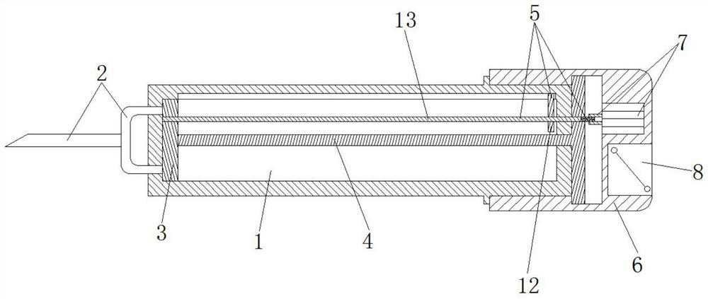
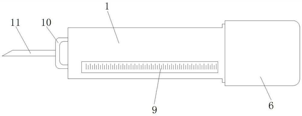
[0023] Such as figure 1 , figure 2 As shown, the booster device for cardiovascular radiography includes a sleeve 1, a liquid discharge mechanism 2, a push plate 3, a push rod 4, a linkage mechanism 5, a connecting sleeve 6, a driving mechanism 7, a lithium battery 8, and a scale 9. The left side of the sleeve 1 is sealed and fixed with a liquid discharge mechanism 2 running through it. The inside of the sleeve 1 is slidingly provided with a push plate 3 on the left side. The right side thread of the push plate 3 is threaded with a push rod 4 . The rod 4 slides through the sleeve 1, the inner upper end of the sleeve 1 slides on the right side and is provided with a linkage mechanism 5, and the right side of the sleeve 1 is tightly fitted and plugged with a connecting sleeve 6, and the connecting sleeve A driving mechanism 7 is fixed inside the sleeve 6, a lithium battery 8 is tightly arranged inside the connecting sleeve 6, and a scale 9 is sealed and fixed inside the front e...
Embodiment 2
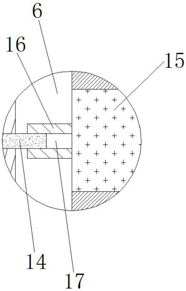
[0026] Such as figure 1 , figure 2 , image 3 As shown, the booster device for cardiovascular radiography includes a sleeve 1, a liquid discharge mechanism 2, a push plate 3, a push rod 4, a linkage mechanism 5, a connecting sleeve 6, a driving mechanism 7, a lithium battery 8, and a scale 9. The left side of the sleeve 1 is sealed and fixed with a liquid discharge mechanism 2 running through it. The inside of the sleeve 1 is slidingly provided with a push plate 3 on the left side. The right side thread of the push plate 3 is threaded with a push rod 4 . The rod 4 slides through the sleeve 1, the inner upper end of the sleeve 1 slides on the right side and is provided with a linkage mechanism 5, and the right side of the sleeve 1 is tightly fitted and plugged with a connecting sleeve 6, and the connecting sleeve 6 is fixed with a driving mechanism 7 inside, the inside of the connecting sleeve 6 is tightly equipped with a lithium battery 8, and the front end of the sleeve 1 ...
PUM
 Abstract
Description
Claims
Application Information
 - R&D
- Intellectual Property
- Life Sciences
- Materials
- Tech Scout
- Unparalleled Data Quality
- Higher Quality Content
- 60% Fewer Hallucinations
Browse by: Latest US Patents, China's latest patents, Technical Efficacy Thesaurus, Application Domain, Technology Topic, Popular Technical Reports.
© 2025 PatSnap. All rights reserved.Legal|Privacy policy|Modern Slavery Act Transparency Statement|Sitemap|About US| Contact US: help@patsnap.com


