Vertical drilling machine device for machining

A vertical drilling machine and mechanical processing technology, applied in metal processing equipment, drilling/drilling equipment, metal processing machinery parts, etc., can solve problems such as low efficiency, and achieve the effect of improving work efficiency and dust collection efficiency

Inactive Publication Date: 2021-01-12
蒋廷道
View PDF0 Cites 0 Cited by
  • Summary
  • Abstract
  • Description
  • Claims
  • Application Information

AI Technical Summary

Problems solved by technology

[0003] At present, there are many kinds of vertical drilling machine equipment for mechanical processing on the market, but these vertical drilling machine equipment generally need to manually move the position of the workpiece on the workbench to drill holes in different positions of the workpiece, and frequent disassembly is required. Fixtures, low efficiency

Method used


Image

  • Vertical drilling machine device for machining
  • Vertical drilling machine device for machining
  • Vertical drilling machine device for machining

Examples


Embodiment 1

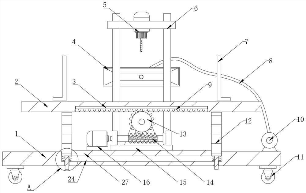
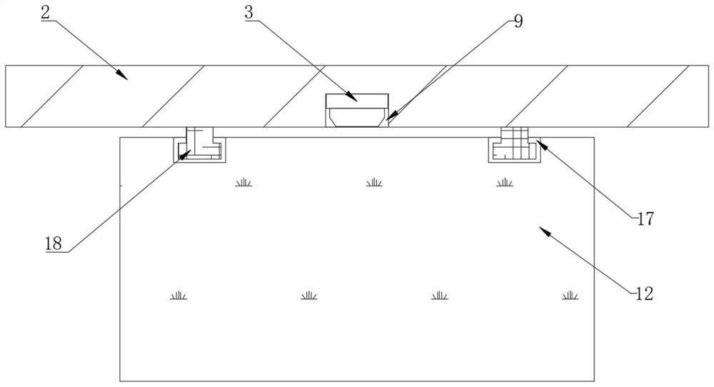
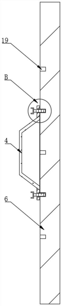
[0027] see Figure 1~5 , in an embodiment of the present invention, a vertical drilling machine equipment for mechanical processing, including a base 1, the four corners of the bottom of the base 1 are connected with moving wheels 11, and the top of the base 1 is connected with two support plates 12, the base 1 The rear part of the top is provided with a frame 6, the top of the frame 6 is equipped with a drilling rig 5, and the tops of the two support plates 12 are jointly connected with a workbench 2, and the top of the workbench 2 is provided with two clamps 7, two support plates 12 is provided with connecting horizontal plate 27, and the top of connecting horizontal plate 27 is equipped with motor 16, and the top of connecting horizontal plate 27 is provided with mounting seat 15, and the top of mounting seat 15 outside is provided with gear 13, and the inboard of mounting seat 15 is installed There is a worm screw 14, the middle position of the bottom end of the workbench ...

Embodiment 2

[0035] refer to figure 1 and 6, a vertical drilling machine used for mechanical processing. Compared with Embodiment 1, this embodiment also includes a second installation groove 24 on the top of the base 1, and several limit positions at equal distances on both sides of the bottom of the base 1. The through hole 25 and the inner sides of the second mounting groove 24 are equidistantly equipped with several damping springs 23 , and the bottom end of the support plate 12 is equidistantly connected with several limit rods 26 .

[0036] Wherein, one end of the shock absorbing spring 23 is connected with the top of the base 1, the other end of the shock absorbing spring 23 is connected with the bottom of the support plate 12, and the limit rod 26 is arranged between the shock absorber spring 23 and the limit through hole 25. internal.

[0037] Working principle: When the drilling machine 5 drills the workpiece, the workpiece will vibrate to a certain extent on the workbench 2. A...


PUM


Abstract

The invention discloses a vertical drilling machine device for machining. The vertical drilling machine device comprises a base, wherein moving wheels are connected to four corners of the bottom end of the base, two supporting plates are connected to the top end of the base, a rack is arranged at the rear part of the top end of the base, a drilling machine is installed at the top of the rack, anda workbench is jointly connected to the top ends of the two supporting plates. According to the vertical drilling machine device, through a sliding block, a sliding groove, a worm, a gear, a motor, amounting seat, a rolling shaft, a first mounting groove and a rack, the position of the workbench can be conveniently and horizontally moved on the two supporting plates, so that different to-be-drilled positions on a workpiece on the workbench can be conveniently drilled by the drilling machine, and the workpiece does not need to be moved on the workbench by manually and frequently disassemblingand assembling a clamp; and the gear and the worm have self-locking performance, so that when the drilling machine drills the workpiece, the position of the workbench cannot deviate, and then the working efficiency of the vertical drilling machine device is improved.

Description

technical field [0001] The invention relates to the technical field of machining equipment, in particular to a vertical drilling machine equipment for machining. Background technique [0002] At present, a drilling machine with a vertically arranged spindle and a fixed center position, referred to as a vertical drill, is often used in machinery manufacturing and repair factories to process holes in small and medium-sized workpieces. Before processing, the position of the workpiece on the workbench must be adjusted so that the processed hole The center line is aligned with the axis of the tool. During processing, the workpiece is fixed, and the spindle rotates in the sleeve and feeds axially with the sleeve. [0003] At present, there are many kinds of vertical drilling machine equipment for mechanical processing on the market, but these vertical drilling machine equipment generally need to manually move the position of the workpiece on the workbench to drill holes in differe...

Claims


Application Information

Patent Timeline
Patent Type & Authority Applications(China)
IPC IPC(8): B23B39/00B23Q11/00
CPCB23B39/00B23Q11/0032B23Q11/0046
Inventor 蒋廷道
Owner 蒋廷道
Why Eureka
Try Eureka