Supercharge Your Innovation With Domain-Expert AI Agents!

Welding dust collection buffer equipment for electromechanical equipment production

A technology of electromechanical equipment and buffer equipment, applied in mechanical equipment, welding equipment, auxiliary welding equipment, etc., can solve problems such as low welding efficiency, unstable welding, and influence on welding effect, so as to improve welding efficiency, ensure stability, and operate easy effect

Inactive Publication Date: 2021-01-12
熊衍金
View PDF0 Cites 0 Cited by
  • Summary
  • Abstract
  • Description
  • Claims
  • Application Information

AI Technical Summary

Problems solved by technology

[0002] Electromechanical equipment is equipment that applies mechanical and electronic technologies, and what is commonly referred to as mechanical equipment is the most important part of electromechanical equipment; there are many types of electromechanical equipment, and there are various classification methods, which can be divided into industrial electromechanical equipment according to their uses. In the production process of electromechanical equipment, it is often necessary to weld the relevant parts of the electromechanical equipment, but the existing welding equipment is inconvenient to adjust the horizontal and vertical positions of the welding head It is time-consuming and labor-intensive to operate the parts, the welding efficiency is low, and the shock absorption effect of the welding equipment is not good, and the welding process is unstable, which will affect the welding effect, and the smoke generated during the welding process will It will cause damage to the health of the operating workers; therefore, we propose a welding dust suction buffer equipment for the production of electromechanical equipment

Method used


Image

  • Welding dust collection buffer equipment for electromechanical equipment production
  • Welding dust collection buffer equipment for electromechanical equipment production
  • Welding dust collection buffer equipment for electromechanical equipment production

Examples


Embodiment Construction

[0032] The following will clearly and completely describe the technical solutions in the embodiments of the present invention with reference to the accompanying drawings in the embodiments of the present invention. Obviously, the described embodiments are only some, not all, embodiments of the present invention. Based on the embodiments of the present invention, all other embodiments obtained by persons of ordinary skill in the art without making creative efforts belong to the protection scope of the present invention.

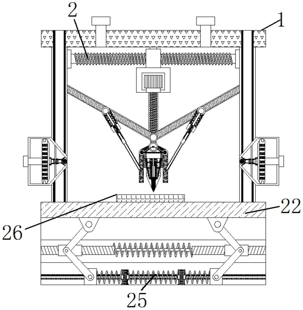
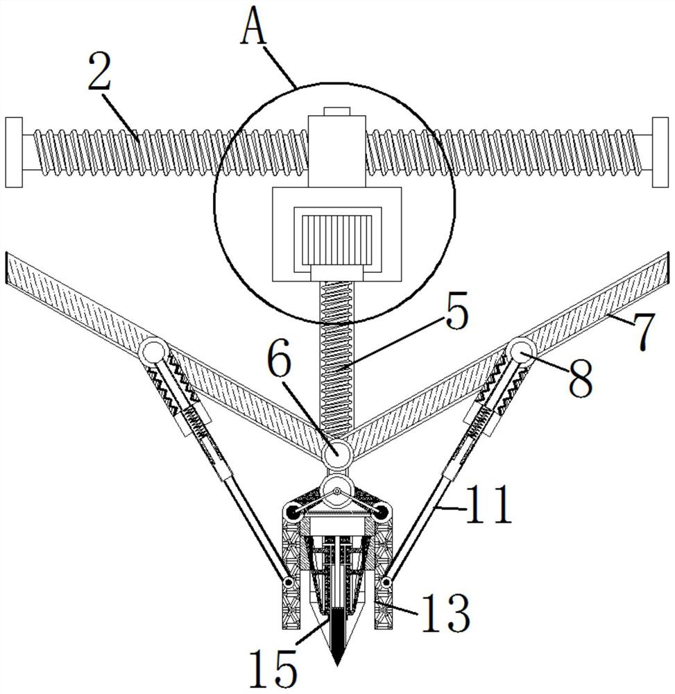
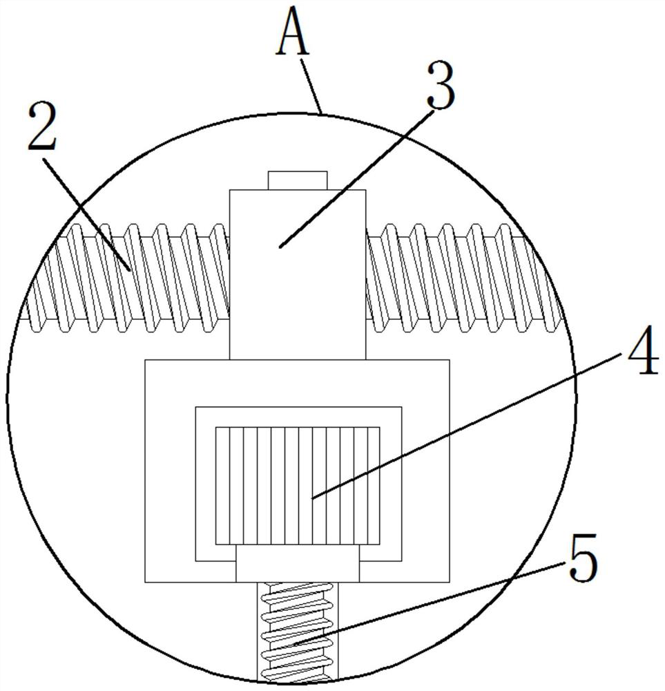
[0033] see Figure 1-9 , a kind of welding vacuum buffer equipment for the production of electromechanical equipment, including a device main body 1, a drive screw 2 is arranged inside the device main body 1, an adapter block 3 is movably connected to the outside of the drive screw 2, and an adapter block 3 is movably connected to the outside There is an adapter axis 4, an adapter screw 5 is movably connected to the outside of the adapter axis 4, and an instal...


PUM


Abstract

The invention relates to the technical field of electromechanics, and discloses welding dust collection buffer equipment for electromechanical equipment production. The equipment comprises an equipment main body. A driving screw rod is arranged inside the equipment main body, an adapter block is movably connected to the outer side of the driving screw rod, an adapter shaft core is movably connected to the outer side of the adapter block, and an adapter screw rod is movably connected to the outer side of the adapter shaft core. A mounting block is movably connected to the end, away from the adapter shaft core, of the adapter screw rod, a connecting rod is movably connected to the outer side of the mounting block, a fixed shaft core is movably connected to the outer side of the connecting rod, and a fixed rod is movably connected to the outer side of the fixed shaft core. According to the welding dust collection buffer equipment for electromechanical equipment production, a bearing plateis arranged on the outer side of a spot welding head, a bearing shaft core, a bearing rod, a fixed spring and the fixed rod are connected to the outer side of the bearing plate, the fixed shaft coreis movably connected to a connecting rod in a clamping manner, and the stability of the spot welding head during welding is kept.

Description

technical field [0001] The invention relates to the field of electromechanical technology, in particular to a welding dust suction buffer device for the production of electromechanical equipment. Background technique [0002] Electromechanical equipment is equipment that applies mechanical and electronic technologies, and what is commonly referred to as mechanical equipment is the most important part of electromechanical equipment; there are many types of electromechanical equipment, and there are various classification methods, which can be divided into industrial electromechanical equipment according to their uses. In the production process of electromechanical equipment, it is often necessary to weld the relevant parts of the electromechanical equipment, but the existing welding equipment is inconvenient to adjust the horizontal and vertical positions of the welding head It is time-consuming and labor-intensive to operate the parts, the welding efficiency is low, and the ...

Claims


Application Information

Patent Timeline
Patent Type & Authority Applications(China)
IPC IPC(8): B23K37/02B23K37/00B08B15/00F16F15/067
CPCB08B15/007B23K37/00B23K37/0252F16F15/067
Inventor 熊衍金
Owner 熊衍金
Features
  • R&D
  • Intellectual Property
  • Life Sciences
  • Materials
  • Tech Scout
  • Unparalleled Data Quality
  • Higher Quality Content
  • 60% Fewer Hallucinations
Learn More