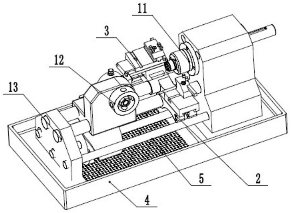
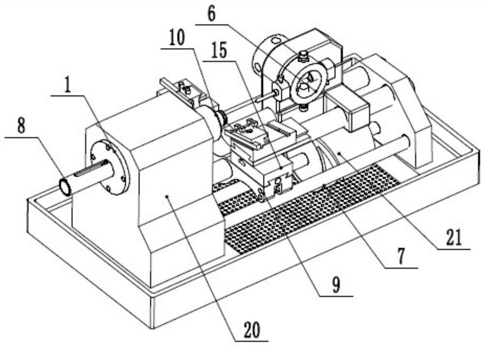
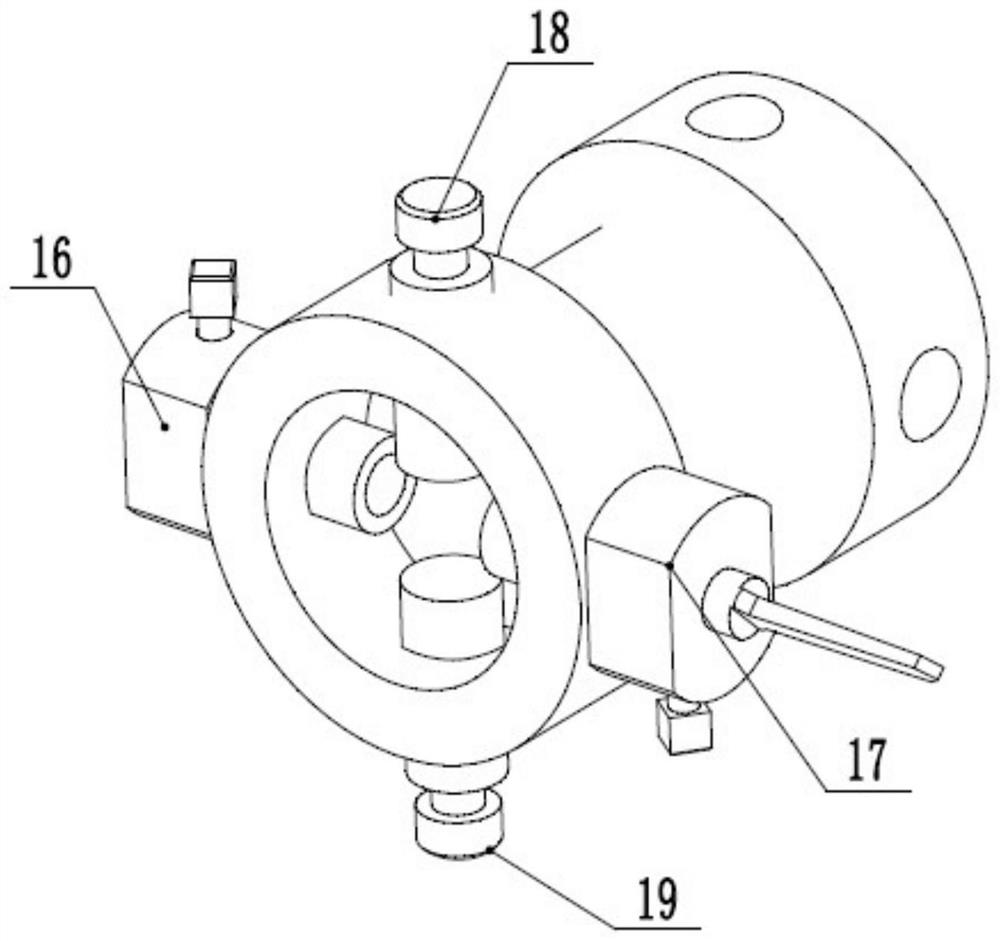
Expansion joint efficient edge grinding device

An expansion joint and high-efficiency technology, which is applied in the direction of grinding drive devices, machine tools suitable for grinding the edge of workpieces, grinding machines, etc., can solve the problems of unclean cleaning, low efficiency, and the failure of the main body of the expansion joint to be inserted into the hole smoothly, and achieve Improve deburring efficiency and ensure effective removal

Pending Publication Date: 2021-01-12
黄玉林
View PDF0 Cites 0 Cited by
  • Summary
  • Abstract
  • Description
  • Claims
  • Application Information

AI Technical Summary

Problems solved by technology

It can also be used for noise reduction, vibration reduction, and heating. In order to prevent the deformation or damage of the pipeline due to thermal elongation or temperature stress when the heating pipeline is heated up, it is necessary to install a compensator on the pipeline to compensate for the thermal elongation of the pipeline. In order to reduce the stress on the pipe wall and the force acting on the valve or bracket structure, the upper and lower ends of the expansion joint are provided with flanges, which are connected and fixed by welding. An opening is set on the hole of the flange, so that the main body of the expansion joint is inserted into the flange and welded at the opening to improve the firmness of the welding. The opening of the flange is cut by a flame cutting machine, and its cutting efficiency High, but when the flame cutting machine cuts the opening, it will leave burrs in the hole. If the burr cannot be removed, the main body of the expansion joint cannot be smoothly inserted into the hole. The existing production process is that the operator uses the angle Grinding the burr manually by the mill is not only inefficient, but also has the situation of unclean cleaning

Method used


Image

  • Expansion joint efficient edge grinding device
  • Expansion joint efficient edge grinding device
  • Expansion joint efficient edge grinding device

Examples


Embodiment Construction

[0021] In order to make the purpose, technical solutions and advantages of the embodiments of the present invention clearer, the technical solutions in the embodiments of the present invention will be clearly and completely described below in conjunction with the drawings in the embodiments of the present invention. Obviously, the described embodiments It is a part of embodiments of the present invention, but not all embodiments. The components of the embodiments of the invention generally described and illustrated in the figures herein may be arranged and designed in a variety of different configurations. Accordingly, the following detailed description of the embodiments of the invention provided in the accompanying drawings is not intended to limit the scope of the claimed invention, but merely represents selected embodiments of the invention. Based on the embodiments of the present invention, all other embodiments obtained by persons of ordinary skill in the art without mak...


PUM


Abstract

The invention relates to the technical field of expansion joint machining devices, in particular to an expansion joint efficient edge grinding device. The expansion joint efficient edge grinding device comprises: a base; wherein the left end and the right end of the base are each provided with a sliding way in the horizontal direction; two fixed clamping blocks, wherein the two fixed clamping blocks are located at the left end and the right end of the base correspondingly, a guide rod matched with the sliding ways is arranged on the inner sides of the upper ends of the fixed clamping blocks inthe horizontal direction, and the fixed clamping blocks are inserted into the corresponding sliding ways on the same side slidably through the guide rod; a second elastic piece, wherein the second elastic piece is arranged in the sliding ways, one end of the second elastic piece is connected with the guide rod, and the other end of the second elastic piece is connected with the base; and a shaftbody, wherein the shaft body is arranged in the vertical direction and is rotatably installed in the center of the base through a bearing, a rocking wheel is installed at the upper end of the shaft body, a sliding bearing frame is arranged at the lower end of the shaft body, and a guide rail groove is horizontally formed in the sliding bearing frame in the left-right direction.

Description

technical field [0001] The invention relates to the technical field of expansion joint processing devices, in particular to a high-efficiency edging device for expansion joints. Background technique [0002] Introduction: Expansion joints are customarily also called compensators, or expansion joints. It is composed of bellows and end pipes, brackets, flanges, conduits and other accessories that constitute the main body of its work. The expansion joint is a flexible structure arranged on the container shell or pipeline in order to compensate the additional stress caused by temperature difference and mechanical vibration. Utilize the effective expansion and contraction deformation of the bellows of its working body to absorb the dimensional changes of pipelines, conduits, containers, etc. caused by thermal expansion and contraction, or compensate the axial, lateral and angular displacement of pipelines, conduits, containers, etc. It can also be used for noise reduction, vibr...

Claims


Application Information

Patent Timeline
Patent Type & Authority Applications(China)
IPC IPC(8): B24B9/04B24B41/02B24B47/12B24B41/00
CPCB24B9/04B24B41/00B24B41/02B24B47/12
Inventor 黄玉林
Owner 黄玉林
Why Eureka
Try Eureka