
Key cooling demoulding mode

A key and demoulding technology, applied in the direction of household components, household appliances, other household appliances, etc., can solve the problem of uneven material flow of key products, prolonged production cycle, increased demolding difficulty and defective demoulding rate of key products And other issues

Pending Publication Date: 2021-01-12
众鼎瑞展电子科技(深圳)有限公司
View PDF2 Cites 1 Cited by
  • Summary
  • Abstract
  • Description
  • Claims
  • Application Information

AI Technical Summary

Problems solved by technology

[0002] Generally, when the silicone rubber or rubber is made of button products, when the silicone rubber or rubber is molded at high temperature, the material properties will be swollen and soft; because the button products will increase the size of the button products due to expansion, and then make the button products larger. Due to the expansion force between it and the forming master mold, the adhesion and friction between it and the forming master mold will increase, so it will increase the difficulty of demoulding and the demoulding defect rate of this button product; and such materials are in the When cured at high temperature, the physical properties of the material will be soft and rotten, inelastic, and the button product will be damaged due to the pulling during demoulding. These are the reasons for the low yield and efficiency of the button product demoulding at high temperature.
[0003] Generally, when the button products are demoulded, manual demoulding and high-pressure air gun cooling are often used, and when manual demoulding, there will be uneven force and the hands of the personnel will suffer from the high temperature of the production mold. When using a high-pressure air gun, because the air gun can only be cooled at a single point and has a certain range, it is difficult to cool the small or deep key products, which will also make the most in need of cooling. The part of the button product that is deeply trapped in the production master mold cannot be effectively cooled, and even the production master mold will be blown by high-pressure air to cool it, and the production master mold will be left for too long due to the difficulty of demoulding. And let this cause a temperature drop, which will make the production master mold need to be heated once before producing the next button product due to uneven mold temperature and insufficient temperature, otherwise it will be caused by uneven mold temperature distribution and insufficient temperature. The button products to be produced next time have some parts that are not ripe enough, and the material leveling of the button products is not uniform, and the production cycle will also be lengthened; especially when the button spacing of the button products is insufficient and the height of the buttons is too high, it is also necessary to increase the number of buttons. The difficulty of demoulding the product; and because the high pressure of the high-pressure air gun will be concentrated on one point, it will still be at a high temperature and its constituent materials have not yet completed the bonding of the material properties of its constituent materials due to cooling For example, in the case of high ductility and high elasticity, the button products will be damaged due to the high pressure blowing of the high-pressure air gun
[0004] On the leftover material of the button product, it is often just to ensure the completion of the finished product of the button product and the convenience of demoulding, and the component material will spread and flow around at high temperature. , which also causes the problem of insufficient film thickness in the film thickness of the leftover material, and such insufficient film thickness will also reduce the high ductility and high elastic material properties of the constituent materials. When molding, it will be damaged from the leftover material due to the uneven application of force, and it is often damaged to the required button product.

Method used


Image

  • Key cooling demoulding mode
  • Key cooling demoulding mode
  • Key cooling demoulding mode

Examples


Embodiment Construction

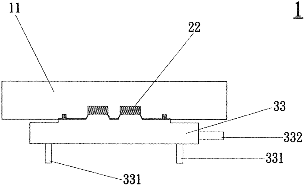
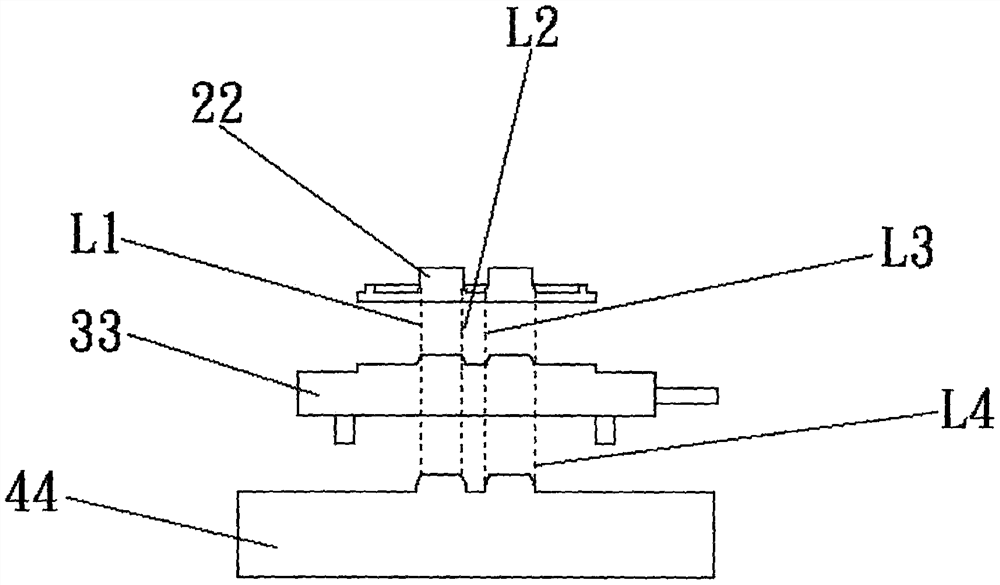
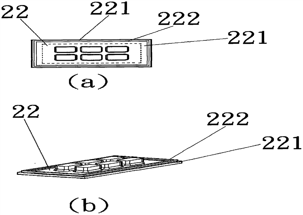
[0014] figure 1 It is a schematic diagram of the combination in the embodiment, and its implementation mode is: when the button product 22 of silicone rubber or rubber is heat-pressed or injection-molded, and the button product 22 is still trapped in the production master mold 11, the vacuum cooling demoulding fixture 33 Because it can be completely attached to the inner wall of the button product 22 and does not touch the production master mold 11, and the vacuum cooling demoulding fixture 33 is made of a material with high thermal conductivity, it can be quickly and only for rapid cooling The button product 22 part of the keypad product 22 is used to derive its high temperature and will not cool down the production master mold 11 because it does not touch the production master mold 11; and a cooling water inlet pipe 331 is provided in its vacuum cooling demoulding fixture 33 , the external cooling water can be imported into its vacuum cooling demoulding tool 33, and the temp...


PUM


Abstract

The invention provides a key cooling demoulding mode. The key cooling demoulding mode comprises a key product, a demoulding edge strip formed at the corner excess material part of the key product andused for avoiding key product damage caused by tearing due to insufficient film thickness at the corner excess material part during demoulding, and at least one vacuum cooling demoulding jig which ismade of a material with a high heat conductivity coefficient and is consistent with a key of a forming male mold in size. The complete attaching to the inner wall of the key product can be realized, avacuum air suction pipeline and a cooling water inlet pipeline are arranged in the jig, and then material expansion and softening of the key product caused by high-temperature curing are quickly andlocally cooled through high thermal conductivity of the material with the high heat conductivity coefficient and the dual cooling of the cooling water inlet pipeline; and meanwhile, the phenomenon that the key product is damaged due to uneven force application during demoulding can be avoided by adopting a vacuum comprehensive air suction mode for demoulding, so that the demoulding yield and demoulding efficiency can be effectively improved by adopting the key cooling demoulding mode.

Description

technical field [0001] The object of the present invention is a kind of button cooling and demoulding mode, especially a kind of physical characteristic (thermal conductivity of material: copper 401Wm) by the high thermal conductivity of high thermal conductivity material -1 K -1 , Aluminum 237Wm -1 K -1 ) and the double rapid local cooling of the cooling water in the button demoulding (button production molds are often made of iron and steel, and the thermal conductivity of the material is iron 80Wm -1 K -1 , Steel 60Wm -1 K -1 ), so the vacuum cooling demoulding fixture uses this double rapid cooling method and its key size is consistent with the key size of the forming male mold, so it can completely fit the inner wall of the key product, and can achieve targeted Let this rapid cooling effect go directly to the depth of the button of the button product; and add a button at the leftover material of the button product composed of silicone rubber or rubber to avoid teari...

Claims


Application Information

Patent Timeline
IPC IPC(8): B29C43/52B29C43/50B29C45/73B29C45/43B29L31/46
CPCB29C43/52B29C43/50B29C45/73B29C45/43B29C2043/5046B29L2031/466
Inventor 高瑞三
Owner 众鼎瑞展电子科技(深圳)有限公司
Learn More