Cryoablation catheter and cryoablation system

An ablation catheter and catheter technology, used in cooling surgical instruments, medical science, surgery, etc., can solve the problems of increasing refrigerant, ablation failure, and increased pressure fluctuation of the cryo-balloon, so as to improve the control accuracy, shorten the operation time, Avoid overshoot-prone effects

Active Publication Date: 2021-03-09
SHANGHAI ARTECHMED MEDICAL TECH CO LTD
View PDF1 Cites 0 Cited by
  • Summary
  • Abstract
  • Description
  • Claims
  • Application Information

AI Technical Summary

Problems solved by technology

[0003] Different shapes and sizes of tissues to be ablated require different cooling capacity for cryoballoon ablation. If the required cryoballoon surface temperature (too high or too low) cannot be obtained during the operation, the ablation may be stopped early, resulting in this failed ablation
The mainstream cryoballoons on the market are usually made of polymer materials (such as PET). At present, the size of the largest cryoballoon is 28mm, and the main unit of the cryoablation system has a fixed flow or cold output to the cryoballoon, which cannot be cooled. Volume control, the pressure resistance of cryoablation system is generally limited in low temperature environment, when cooling capacity or flow output is required, or when larger cooling capacity or larger size cryoballoon is required, the main unit of the cryoablation system will increase the cooling capacity. The cooling amount or flow rate of the agent will increase the pressure fluctuation inside the cryoballoon, increasing the risk of cryoballoon rupture
Moreover, in the traditional cryoballoon cryoablation catheter, the return path of the refrigerant has only a single cavity, and the accuracy of the single cavity to adjust the internal pressure of the cryoballoon by controlling the return proportional valve is too low, and it is easy to overshoot, which affects the cryoablation. Ablation Safety

Method used


Image

  • Cryoablation catheter and cryoablation system
  • Cryoablation catheter and cryoablation system
  • Cryoablation catheter and cryoablation system

Examples


Embodiment Construction

[0027] The specific implementation manner of the present invention will be described in more detail below with reference to schematic diagrams. The advantages and features of the present invention will be more apparent from the following description. It should be noted that all the drawings are in a very simplified form and use imprecise scales, and are only used to facilitate and clearly assist the purpose of illustrating the embodiments of the present invention.

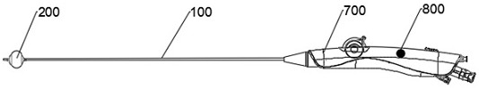
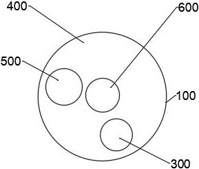
[0028] Such as figure 1 and figure 2 As shown, this embodiment provides a cryoablation catheter, which includes a catheter body 100 and a cryoballoon 200. The catheter body 100 is provided with an inlet refrigerant chamber 300, a main return chamber 400, and several auxiliary return chambers 500. The inlet refrigerant cavity 300 , the main return cavity 400 and the auxiliary return cavity 500 are all in communication with the cryoballoon 200 , and the auxiliary return cavity 500 is used to assist in regulating t...


PUM


Abstract

The present invention provides a cryoablation catheter and a cryoablation system. The cryoablation catheter includes a catheter body and a cryoballoon. The catheter body is provided with an inlet refrigerant chamber, a main return chamber and several auxiliary return chambers. The refrigerant inlet cavity, the main return cavity and the auxiliary return cavity are all in communication with the cryoballoon, and the auxiliary return cavity is used to assist in regulating the pressure in the cryoballoon. On the basis of realizing the adjustable and controllable cold capacity of the cryoablation catheter, by adopting the form of multi-cavity reflux, the internal pressure of the cryoballoon is regulated and stabilized, ensuring that the internal pressure of cryoballoons of various sizes is within the safe use range , to achieve the safe use of cryoablation catheters of various specifications in clinical practice, and to meet the personalized treatment of different needs. In addition, by adding an auxiliary recirculation chamber, the control accuracy of the flow rate can be improved, the problem of easy overshoot when adjusting a single chamber can be avoided, and the safety of cryoablation can be improved.

Description

technical field [0001] The invention relates to the technical field of cryoablation, in particular to a cryoablation catheter and a cryoablation system. Background technique [0002] Cryoablation, often used to treat various arrhythmias or nerve ablation, including atrial fibrillation, renal artery ablation, etc. For example, many arrhythmias are caused by or involve abnormal electrical currents conducted through cardiac tissue. In cryoablation, the tissue is cooled through the cryoablation catheter until the abnormal electrical conduction is eliminated or otherwise deemed to be improved, thereby eliminating the risk of cardiac arrhythmia. For example, some abnormal currents may originate within one or more pulmonary veins, in which case the ostia or sinuses of the pulmonary veins may be frozen until abnormal current conduction in the pulmonary veins is isolated from the left atrium or other cardiac tissue. [0003] Different shapes and sizes of tissues to be ablated requi...

Claims


Application Information

Patent Timeline
Patent Type & Authority Patents(China)
IPC IPC(8): A61B18/02
CPCA61B18/02A61B2018/0022A61B2018/00714A61B2018/00744A61B2018/0262
Inventor 梅勤智曹海朋李雷李立夫史胜凤薛卫
Owner SHANGHAI ARTECHMED MEDICAL TECH CO LTD
Why Eureka
Try Eureka