
Grain stone-removing jigger

A stone jig and grain technology, applied in the field of jigs, can solve problems such as the impact of production equipment, achieve better efficiency, uniform distribution, and improve control accuracy

Pending Publication Date: 2021-01-15
南通方驰机械有限公司
View PDF0 Cites 0 Cited by
  • Summary
  • Abstract
  • Description
  • Claims
  • Application Information

AI Technical Summary

Problems solved by technology

Due to the residual stones and impurities, it will have a great impact on the subsequent production equipment

Method used


Image

  • Grain stone-removing jigger
  • Grain stone-removing jigger
  • Grain stone-removing jigger

Examples


Embodiment 1

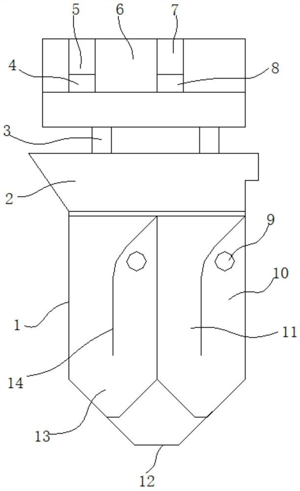
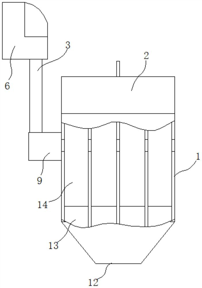
[0039] Such as figure 1 and figure 2 As shown, a grain stone removal jig machine includes a compressed air source, a bellows 6 and a jigging chamber 1 with a screening stone removal groove 2 at the top and a sieve material outlet 12 at the bottom;

[0040] The bellows 6 is provided with an air inlet end 4, an air outlet end 7 and an air supply end 3, an air inlet valve 5 is arranged on the air inlet end 4, an air outlet valve 8 is arranged on the air outlet end 7, and the compressed air source passes through the air duct Connect to the air inlet 4;

[0041] The jigging chamber 1 is provided with a ventilation duct 9, one end of the ventilation duct 9 is blocked, and the other end extends out of the jigging chamber 1, and is connected to the air supply end 3 through the air duct;

[0042] A plurality of independent jigging chambers 13 are evenly distributed in the jigging chamber 1. The top of each independent jigging chamber 13 is connected to the screening stone removal ta...

Embodiment 2

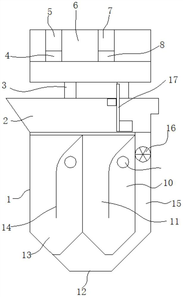
[0050] On the basis of Example 1, such as image 3As shown, the side wall of the jigging chamber 1 is provided with a sorting impurity channel 15 with two ends respectively connected to the discharge port 12 of the sieved material and the discharge end of the screening and stone removal tank 2, and the sorting impurity channel 15 is provided with a discharge device, a bed thickness detection device 17 is arranged in the screening stone removal tank 2, the bed thickness detection device 17 and the discharge device are respectively electrically connected to the controller, and the controller obtains the bed thickness signal fed back by the bed thickness detection device 17 to control The discharge device operates to discharge the sorting impurities in the jigging chamber 1 through the sorting impurity channel 15 .

[0051] Preferably, the bed thickness detection device 17 adopts a bed thickness sensor.

[0052] Preferably, the discharge device adopts a discharge impeller 16 . ...


PUM


Abstract

The invention discloses a grain stone-removing jigger which comprises a compressed air source, an air bellow and a jigging chamber, wherein a screening stone-removing groove is formed in the top of the jigging chamber, and a screen-penetrating material discharging port is formed in the bottom of the jigging chamber; an air inlet end, an air outlet end and an air supply end are arranged on the airbellow, an air inlet valve is arranged at the air inlet end, an air outlet valve is arranged at the air outlet end, and the compressed air source is connected with the air inlet end through an air pipe; a ventilating pipeline is arranged in the jigging chamber, one end of the ventilating pipeline is blocked, and the other end extends out of the jigging chamber and is connected with the air supplyend through an air pipe; and a plurality of independent jigging cavities are evenly distributed in the jigging chamber, the top of each independent jigging cavity communicates with the screening stone-removing groove, the bottom of each independent jigging cavity is open and leads to the screen-penetrating material discharging port, a partition plate dividing the independent jigging cavity into anair cavity and a water cavity is arranged in each independent jigging cavity, and the air cavities communicate with the ventilation pipeline in parallel. By adopting a water flow pulsation principle,grains are effectively separated from impurities and gravels, the gravel and impurity removal efficiency is better, equipment enlargement can be realized, and the production efficiency is improved.

Description

technical field [0001] The invention relates to a jigging machine, in particular to a grain stone removing jigging machine. Background technique [0002] At present, it is the stone removal equipment for various food processing and sugar and alcohol projects in China and even in the world. Basically, they are self-installed swirl pavement and stone removal equipment made of water flushing chutes and hydrocyclone separation theory. This series of equipment has low efficiency and poor stone removal effect. Take the deep processing of corn as an example: only 16.67% of the stones and impurities in the corn can be removed, and at the same time, a large amount of corn is contained in the removed stones and impurities, accounting for 2.9%. Due to the residual stones and impurities, it will have a great impact on the subsequent production equipment. Contents of the invention [0003] Aiming at the defects in the prior art, the present invention provides a grain stone removal de...

Claims


Application Information

Patent Timeline
IPC IPC(8): B03B5/20B03B5/24
CPCB03B5/20B03B5/24
Inventor 倪建校
Owner 南通方驰机械有限公司
Learn More