
Honing method and device based on visual positioning

A visual positioning and honing technology, applied in the field of honing processing, can solve the problems such as the large influence of honing processing accuracy and processing efficiency clamping error, and the inability of the honing machine to accurately and quickly locate the honing holes, so as to improve the honing processing accuracy and stability, Large machining and clamping errors, the effect of increasing honing accuracy

Inactive Publication Date: 2021-01-15
SYMG SHANGHAI INTELLIGENCE SYST CO LTD
View PDF7 Cites 0 Cited by
  • Summary
  • Abstract
  • Description
  • Claims
  • Application Information

AI Technical Summary

Problems solved by technology

[0006] In view of the above-mentioned shortcomings of the prior art, the purpose of the present invention is to provide a honing method and device based on visual positioning, which is used to solve the problem that the honing machine in the prior art cannot accurately and quickly locate the center of the honing hole when performing batch processing. The problem that the honing processing accuracy and processing efficiency are greatly affected by the clamping error

Method used


Image

  • Honing method and device based on visual positioning
  • Honing method and device based on visual positioning
  • Honing method and device based on visual positioning

Examples


Embodiment Construction

[0030] Embodiments of the present invention are described below through specific examples, and those skilled in the art can easily understand other advantages and effects of the present invention from the content disclosed in this specification. The present invention can also be implemented or applied through other different specific implementation modes, and various modifications or changes can be made to the details in this specification based on different viewpoints and applications without departing from the spirit of the present invention. It should be noted that, in the case of no conflict, the following embodiments and features in the embodiments can be combined with each other.

[0031] It should be noted that the diagrams provided in the following embodiments are only schematically illustrating the basic ideas of the present invention, and only the components related to the present invention are shown in the diagrams rather than the number, shape and shape of the compo...


PUM


Abstract

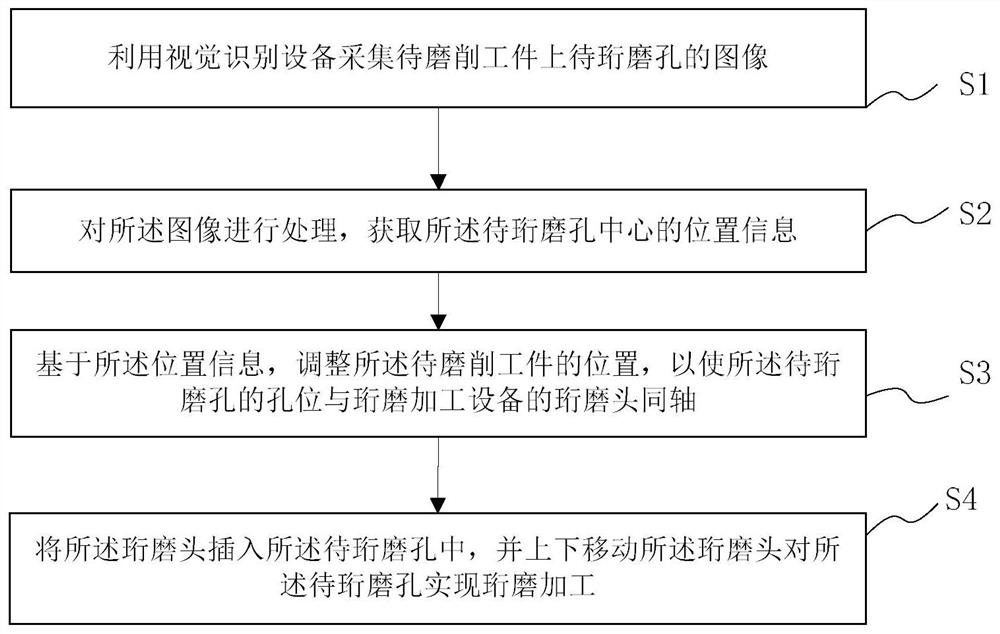
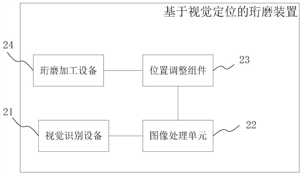
The invention provides a honing method and device based on visual positioning. The honing method based on visual positioning comprises the following steps of collecting an image of a to-be-honed holein a workpiece to be ground by using visual recognition equipment; processing the image, and obtaining position information of the center of the to-be-honed hole; based on the position information, adjusting the position of the workpiece to be ground to enable the hole position of the to-be-honed hole to be coaxial with a honing head of honing processing equipment; and inserting the honing head into the to-be-honed hole, and vertically moving the honing head to perform honing processing on the to-be-honed hole. The honing method and device based on visual positioning provided by the inventionhave the advantages that the center position of the to-be-honed hole can be accurately positioned; the honing precision and stability are improved; during image collection, the center position of to-be-honed hole can be positioned only by presetting the approximate position of the workpiece to be ground, then, the automatic positioning and processing are completed; great processing and clamping errors of the workpiece to be ground can be allowed; in addition, the coaxiality of the honing head and the to-be-honed hole can be ensured; and the honing precision during great-batch processing is greatly improved.

Description

technical field [0001] The invention belongs to the technical field of honing processing, in particular to a honing method and device based on vision positioning. Background technique [0002] Honing is the finishing process of the finished surface with the oil stone (also called honing bar) embedded in the honing head. It is mainly used for aperture grinding of honed workpieces in manufacturing industries such as automobiles, tractors, hydraulic parts, bearings, and aviation. , during honing, the workpiece is installed on the honing machine table or in the fixture, and the honing head with a number of honing stones is inserted into the processed hole, driven by the main shaft of the machine tool to rotate and reciprocate in the axial direction, and the honing stone is pressed against the hole wall with a certain pressure. Contact can cut off a very thin layer of metal. [0003] Hole honing is an efficient processing method with high precision, high surface quality, and lar...

Claims


Application Information

Patent Timeline
Patent Type & Authority Applications(China)
IPC IPC(8): B24B33/02B24B33/06B24B33/10
CPCB24B33/027B24B33/06B24B33/10
Inventor 朱志浩邓肖李兴隆陈阁
Owner SYMG SHANGHAI INTELLIGENCE SYST CO LTD
Learn More