Electric multi-rotor unmanned aerial vehicle with mixed large and small rotors

A multi-rotor UAV and UAV technology, applied in the field of aircraft, can solve the problems of reduced response speed, increased difficulty in attitude control, and bombing, so as to make up for the reduced control performance, ensure fast response, and increase flight. effect of time

Pending Publication Date: 2021-01-15
北京韦加智能科技股份有限公司
View PDF0 Cites 0 Cited by
  • Summary
  • Abstract
  • Description
  • Claims
  • Application Information

AI Technical Summary

Problems solved by technology

As a result, as the size of the rotor increases, the power of the motor increases exponentially, correspondingly requiring a battery with a larger capacity and heavier weight, which leads to a simultaneous increase in the weight of the drone itself.
The disadvantage of this kind of power system is that the final increased load capacity or flight time is not proportional to the total cost, that is, as the power increases, it becomes more and more uneconomical and the cost performance becomes worse and worse.
[0004] If you do not use a motor with higher power and higher torque to drive, but on the basis of the matched motor and propeller in the full speed range, the motor remains unchanged and the size of the propeller increases, then it will not be able to provide large propellers at the highest speed. The high torque required, so there will be a dangerous situation of high-speed rotation and stall, which will eventually lead to the bombing
In the speed range without stalling, due to the large moment of inertia of the large rotor, the response speed will be reduced and the attitude control will be more difficult

Method used


Image

  • Electric multi-rotor unmanned aerial vehicle with mixed large and small rotors
  • Electric multi-rotor unmanned aerial vehicle with mixed large and small rotors
  • Electric multi-rotor unmanned aerial vehicle with mixed large and small rotors

Examples


Embodiment Construction

[0022] The principles and features of the technical invention will be described below in conjunction with the accompanying drawings, and the examples given are only used to explain the present invention, and are not intended to limit the scope of the technical invention. It should be noted that, in the case of no conflict, the embodiments of the present application and the features in the embodiments can be combined with each other.

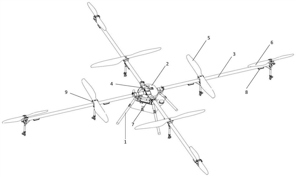
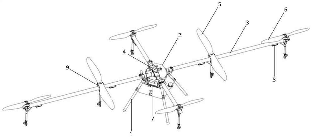
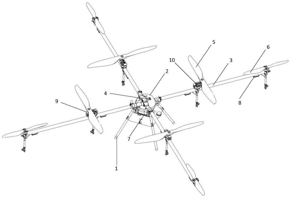
[0023] like figure 1 As shown, the present invention is a multi-rotor UAV with a mixture of large and small rotors. When the motor remains unchanged, the large rotor has a large lift and slow response, and the small rotor has a fast response and small lift. Stability control with attitude. The present invention is an eight-rotor unmanned aerial vehicle with mixed large and small rotors directly driven by large paddles, which includes: landing gear 1, cabin 2, machine arm 3, flight control system 4, four large rotors 5, four small rotors 6, Lith...


PUM


Abstract

The invention discloses an electric multi-rotor unmanned aerial vehicle with mixed large and small rotors. The electric multi-rotor unmanned aerial vehicle comprises a vehicle body, undercarriages, vehicle arms, motors, rotors and a flight control system, wherein the motors and the rotors are arranged on the vehicle arms. The rotor wings comprise two or four large rotor wings and four small rotorwings. The flight control system controls the rotation of the two or four large rotors and the four small rotors at the same time; the two or four large rotors provide main lift force for the unmannedaerial vehicle, and the four small rotors provide residual lift force for the unmanned aerial vehicle and are responsible for attitude control of the unmanned aerial vehicle. According to the electric multi-rotor unmanned aerial vehicle with the mixed large and small rotors, the flight time can be prolonged while the load is increased; the unmanned aerial vehicle can be applied to the fields of agricultural plant protection, high-rise fire extinguishing, logistics transportation and the like.

Description

technical field [0001] The invention relates to the technical field of aircraft, in particular to an electric multi-rotor unmanned aerial vehicle with mixed large and small rotors. Background technique [0002] UAV is a general term for unmanned aerial vehicles. It is equipped with autopilot, program control device and other equipment, and can be operated and controlled by ground station terminal or remote control. Compared with manned aircraft, it has the advantages of small size, low cost, and convenient use. It can take off vertically, take off and land automatically, and can be used repeatedly. It has been widely used in various industries. [0003] At present, for electric multi-rotor drones mainly used for spraying operations, in order to increase the load capacity and flight time, larger rotors are required to provide greater lift. Larger rotors require higher power and higher torque motors. As a result, as the size of the rotor increases, the power of the motor in...

Claims


Application Information

Patent Timeline
IPC IPC(8): B64C27/08B64C27/12B64D27/24B64D31/00B64D35/00
CPCB64C27/08B64C27/12B64D27/24B64D31/00B64D35/00B64U50/19B64U10/10Y02T50/60
Inventor 罗兵王梦龙张先敏逯亮清
Owner 北京韦加智能科技股份有限公司
Why Eureka
Try Eureka