Cotton spinning frame with increased twist in twist zone for textile use and intelligent manufacturing method

A spinning frame and cotton spinning technology, applied in the direction of spinning machines, textiles and papermaking, continuous winding spinning machines, etc., can solve the problem of not having a cotton wool collection structure, adjusting the distance of the cotton spinning frame, and reducing the application of cotton spinning frames Scope and other issues to achieve the effect of improving the scope of application

Active Publication Date: 2021-06-01
宿迁大汉纺织有限公司
View PDF8 Cites 0 Cited by
  • Summary
  • Abstract
  • Description
  • Claims
  • Application Information

AI Technical Summary

Problems solved by technology

[0004] The existing cotton spinning frames with increased twist area twist for textile use have certain disadvantages in the process of use. The cotton spinning frame with increased twist area twist for traditional textiles adopts a fixed structure design, so that the cotton spinning frame with increased twist area twist for traditional textiles The spinning frame cannot adjust the reading distance of the cotton spinning frame according to the diameter of the bobbin, so that the traditional cotton spinning frame cannot be applied to different types of bobbin structures, which reduces the flexibility of the cotton spinning frame in use; secondly, the traditional cotton spinning frame does not It has a lifting adjustment structure, so that the cotton spinning frame cannot flexibly adjust its use height according to the needs of use, which reduces the scope of application of the cotton spinning frame for increasing the twist area twist; It has a lint collection structure, and some lint will be produced during the twisting process of the cotton thread. When using the traditional cotton spinning frame for twisting operation, the user needs to regularly clean up the produced lint, thereby reducing the use effect of the cotton spinning frame. have certain adverse effects

Method used


Image

  • Cotton spinning frame with increased twist in twist zone for textile use and intelligent manufacturing method
  • Cotton spinning frame with increased twist in twist zone for textile use and intelligent manufacturing method
  • Cotton spinning frame with increased twist in twist zone for textile use and intelligent manufacturing method

Examples


Embodiment Construction

[0031] The technical solutions in the embodiments of the present invention will be clearly and completely described below in conjunction with the embodiments of the present invention. Apparently, the described embodiments are only some of the embodiments of the present invention, not all of them. Based on the embodiments of the present invention, all other embodiments obtained by persons of ordinary skill in the art without creative efforts fall within the protection scope of the present invention.

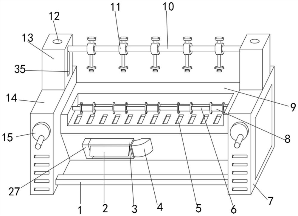
[0032] like Figure 1-5 As shown, a cotton spinning frame for increasing the twist in the twist zone for weaving includes a processing table 9, a second connecting rod 10 and a dust collection cover 3, and a second box 14 is fixedly installed on the outer surface of one end of the processing table 9, and the processing The outer surface of the other end of the table 9 is fixedly installed with a first box body 7, and the upper positions of the front ends of the first box body 7 an...


PUM


Abstract

The invention discloses a cotton spinning frame and an intelligent manufacturing method for increasing the twist in the twist area for textile use. The outer surface of the other end of the processing table is fixedly installed with a first box body, and the upper positions of the front ends of the first box body and the second box body are both movably installed with a first turntable, and the second connecting rod is movably installed on the processing table Above, the outer surfaces of the upper ends of the second box and the first box are fixedly equipped with a support platform, and the inner middle part of the support platform is movably installed with a first screw rod, and the outer surfaces of both ends of the second connecting rod are Both are fixedly installed with lifting spiral rings; the cotton spinning frame for increasing the twist in the twist area has a lifting adjustment structure, so that it can be applied to different sizes of bobbins, and its scope of application is improved. At the same time, it has a dust-absorbing structure to improve its use effect.

Description

technical field [0001] The invention belongs to the technical field of spinning frame equipment, and more specifically relates to a cotton spinning spinning frame for increasing the twist in the twist zone for textile use. Background technique [0002] The spinning frame is a spinning machine that draws, twists and winds the semi-finished roving or sliver into a spun bobbin during the spinning process. The combed sliver is made, the sliver is combined by the needle carding machine, the needle row drafting improves the sliver structure, and the roving is further twisted and spun into spun yarn on the ring spinning frame, which is the main machine for spinning. [0003] A spinning frame disclosed in the comparative document CN208815201U belongs to the field of textile machinery and includes a spinning frame body. Columns extending vertically upward and higher than the spinning frame body are arranged on both sides of the spinning frame body. Fan, the suction port end of the s...

Claims


Application Information

Patent Timeline
Patent Type & Authority Patents(China)
IPC IPC(8): D01H11/00D01H1/18D01H1/36
CPCD01H1/18D01H1/36D01H11/005
Inventor 虞琴
Owner 宿迁大汉纺织有限公司
Why Eureka
Try Eureka