Cloth dyeing equipment for textile processing

A technology for dyeing equipment and fabrics, which is applied to textile processing machine accessories, textile material processing, and textile material drums, etc. It can solve the problems of inability to adjust the size of a single dyeing, lack of adjustment devices in dyeing equipment, and low work efficiency. It is easy to add dyes, improve the dyeing effect, and facilitate maintenance and cleaning.

Inactive Publication Date: 2021-01-15
张美
0 Cites 3 Cited by

AI-Extracted Technical Summary

Problems solved by technology

[0003] However, in the existing technology, the dyeing equipment lacks an adjustment device, and the size of a single dyeing cannot ...

Method used

Described blowing device blower comprises ventilation duct 7 and air outlet plate 14, and described air outlet plate 14 is fixedly installed on cloth top and its side near cloth is semicircular structure, and described air outlet plate 14 inside offers There is a ventilating chamber and the side close to the cloth also offers multiple sets of air outlet holes communicating with the ventilating chamber. One end of the ventilating pipe 7 is connected to the top of the air outlet plate 14 and the other end passes through the side wall of the box body 12 and is fixed. The blower 21 that is installed on the outer wall of the casing 12 is arranged in communication; the blower 21 blows air to the inside of the ventilation chamber through the ventilation pipe 7, and the wind evenly blows to the cloth through the air outlet, so that the cloth is quickly air-dried.
Described casing 12 side walls are provided with chamber door 3 and chamber door 3 is corresponding with dyestuff box and dyeing assembly position; Open chamber door 3, be convenient to take out dyestuff box and add dyestuff, can also check in time and clean dyeing simultaneously components to ensure the dyeing efficiency of the device.
Described feeding device also comprises feeding roller 8 and carrier roller 22, and the quantity of described feeding roller 8 is multiple groups and is installed in rotation below the cloth, for auxiliary feed roller 2 and discharge roller 9 Conveying the cloth forward is convenient for dyeing and air-drying; the number of the supporting rollers 22 is two groups and is rotatably installed on the side wall of the return chamber 13, and cooperates with the air outlet plate 14 to facilitate the air-drying of the cloth.
Described feeding device comprises feed roller 2, discharge roller 9 and driving motor 23, and described feed roller 2 and discharge roller 9 quantity are two groups and are respectively positioned at feed port 1 and discharge port Near 10, the feed roller 2 and the discharge roller 9 are rotated and installed on the side wall of the box body 12 and are symmetrically distributed on both sides of the cloth, and one end of the feed roller 2 and the discharge roller 9 passes through the box respectively 12 side walls are set in linkage with two sets of drive motors 23 fixedly installed on the outer wall of the box body 12, and meshing gear sets are fixedly installed on the feed roller 2 and the discharge roller 9 respectively, and the feed roller 2 and the discharge roller The periphery of the roller 9 is equipped with a rubber sleeve 20; the drive motors 23 of the two groups drive the feed roller 2 and the discharge roller 9 to rotate through the meshing gear set respectively, so as to realize the conveying of the cloth, which is convenient for the cloth to enter and exit the box body 12, and utilize rubber Cover 20 clamps cloth, prevents cloth from slipping, makes cloth smooth simultaneously, is convenient to dyeing.
During work, by rotating the rotating supp...

Abstract

The invention discloses cloth dyeing equipment for textile processing. The equipment comprises a box body and a dyeing assembly arranged in the box body, the dyeing assembly comprises a clamping device, a dye box and an air blowing device, the dye box is placed at the bottom of the box body, the interior of the dye box is divided into a dyeing cavity and a backflow cavity, and the backflow cavitycommunicates with the dyeing cavity through a backflow pipe provided with a backflow pump. The clamping device comprises dyeing lifting rods, a dyeing supporting plate, bidirectional telescopic rods,dyeing baffles, clamping telescopic rods and dyeing rollers. The dyeing baffles and the dyeing rollers are adopted and cooperate with the clamping telescopic rods and supporting telescopic rods, clothwith different thicknesses can be clamped, meanwhile, the dyeing length of the cloth is adjusted, meanwhile, dyeing missing caused by clamping of the cloth is avoided, and the dyeing efficiency is improved; the dyeing lifting rods are adopted, so that the cloth moves up and down in dye and is in full contact with the dye, and the dyeing effect is improved; and a blower and a ventilation pipe areadopted, a ventilation cavity and air outlet holes are used for uniformly blowing air to the cloth, and the cloth is quickly air-dried.

Application Domain

Textile treatment containersLiquid/gas/vapor treatment machines driving mechanisms +4

Technology Topic

DyeingEngineering +3

Image

  • Cloth dyeing equipment for textile processing
  • Cloth dyeing equipment for textile processing
  • Cloth dyeing equipment for textile processing

Examples

  • Experimental program(2)

Example Embodiment

[0024] Example 1
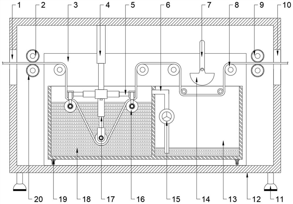
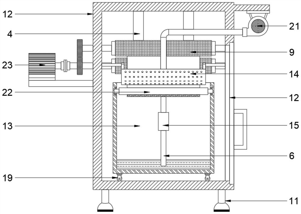
[0025] see Figure 1~4 , in the embodiment of the present invention, a fabric dyeing equipment for textile processing, comprising a box body 12 and a dyeing assembly arranged inside the box body 12, the two sides of the box body 12 are respectively provided with a material inlet 1 and a material outlet 10 And it is also provided with a feeding device inside to facilitate the input and output of fabrics; the dyeing assembly includes a clamping device, a dye box and a blowing device, and the dye box is placed at the bottom of the box body 12 and its interior is divided into dyeing chambers 18 And return chamber 13, described return chamber 13 communicates with dyeing chamber 18 through return pipe 6 and is also provided with return pump 15 on return pipe 6; The upper end of described clamping device is fixedly installed on the box body 12 top and its lower end is positioned at dyeing chamber 18 inside, the blowing device is fixedly installed on the side wall of the box body 12 and is located above the return chamber 13; It is fixedly installed on the top of the box body 12 and its bottom is fixedly connected with a dyeing support plate 27. The number of the two-way telescopic rods 5 is two groups and is fixedly installed on the two ends of the dyeing support plate 27 respectively. The dyeing baffle 26 is fixedly installed at the outlet end and the clamping telescopic rod 24 is fixedly installed at both ends of the dyeing baffle 26. The number of the dyeing rollers 16 is two groups and its two ends are rotatably connected with the clamping telescopic rod 24. The bottom of the dyeing support plate 27 is also movably clamped with a supporting telescopic rod 17 through a dovetail groove structure, the bottom of the supporting telescopic rod 17 is fixedly equipped with a dyeing bracket 25 and a dyeing roller 16 is rotatably arranged on the dyeing bracket 25 .
[0026] Place the dye in the dyeing chamber 18, feed the cloth from the feed port 1 into the box 12 and use the feeding device to drive the cloth forward; adjust the clamping telescopic rod 24 according to the thickness of the cloth, and use the dyeing baffle 26 and the dyeing roller 16 to Clamp the cloth, adjust the supporting telescopic rod 17 according to the length of dyeing, use the dyeing roller 16 on the dyeing bracket 25 to spread the cloth, and the dyeing lifting rod 4 is extended to soak the cloth into the dye, in order to make the cloth fully contact with the dye , the dyeing lifting rod 4 is telescopic, so that the cloth moves up and down in the dye to improve the dyeing effect; the dyed cloth is quickly air-dried through the blowing device by using the feeding device, and the dye is dripped from the cloth into the return cavity 13 during the air-drying process. The backflow pump 15 and the backflow pipe 6 send the dye back to the dyeing chamber 18; finally, the box body 12 is output from the discharge port 10.
[0027] The blower of the blowing device includes a ventilation pipe 7 and an air outlet plate 14, the air outlet plate 14 is fixedly installed above the cloth and its side close to the cloth is in a semicircular structure, and the inside of the air outlet plate 14 is provided with a ventilation cavity And its side close to the cloth is also provided with multiple groups of air outlet holes communicating with the ventilation cavity. One end of the ventilation pipe 7 is connected to the top of the air outlet plate 14 and the other end passes through the side wall of the box body 12 and is fixedly installed in the box. The blower 21 on the outer wall of the body 12 is arranged in communication; the blower 21 blows air to the inside of the ventilation chamber through the ventilation pipe 7, and the wind evenly blows to the cloth through the air outlet, so that the cloth is quickly air-dried.
[0028] The feeding device includes a feed roller 2, a discharge roller 9 and a drive motor 23, and the feed roller 2 and the discharge roller 9 are in two groups and are respectively located near the feed port 1 and the discharge port 10, The feed roller 2 and the discharge roller 9 are all rotated and installed on the side wall of the box body 12 and distributed symmetrically on both sides of the cloth, and one end of the feed roller 2 and the discharge roller 9 passes through the side wall of the box body 12 respectively. Set in linkage with two sets of driving motors 23 fixedly installed on the outer wall of the box body 12, the feed roller 2 and the discharge roller 9 are respectively fixedly equipped with meshing gear sets, and the feed roller 2 and the discharge roller 9 are peripherally The two groups of drive motors 23 drive the feed roller 2 and the discharge roller 9 to rotate through the meshing gear sets respectively, so as to realize the conveying of the cloth, which is convenient for the cloth to enter and exit the box body 12. The fabric is clamped to prevent the fabric from slipping while keeping the fabric flat for easy dyeing.
[0029] The feeding device also includes a feeding roller 8 and a carrier roller 22, the number of the feeding rollers 8 is multiple groups and is rotatably installed below the cloth for auxiliary feed roller 2 and discharge roller 9 to convey forward The cloth is convenient for dyeing and air-drying; the number of the supporting rollers 22 is two groups and is rotatably installed on the side wall of the return chamber 13, and cooperates with the air outlet plate 14 to facilitate the air-drying of the cloth.
[0030]Described box body 12 sidewalls are provided with box door 3 and box door 3 is corresponding with dye box and dyeing assembly position; Open box door 3, be convenient to take out dye box and add dyestuff, can also check and clean dyeing assembly in time simultaneously, with Ensure the dyeing efficiency of the device.
[0031] In order to facilitate the dye box into and out of the box door 3, the bottom of the dye box is also provided with four sets of rollers 19, which are in rolling contact with the bottom of the box door 3 to reduce friction and facilitate the movement of the dye box.
[0032] The bottom of the box body 12 is provided with four sets of supporting legs 11, the supporting legs 11 are composed of a supporting rod and a supporting block, one end of the supporting rod is fixedly connected with the bottom of the casing 12 and the other end is screwed with the supporting block, so The bottom of the support block is also provided with an anti-slip pad; utilize the support leg 11 to support the device, and utilize the anti-slip pad to increase the friction with the ground to prevent sliding. The length is fine-tuned to keep the device stable.

Example Embodiment

[0033] Example 2
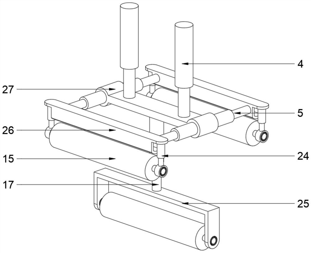
[0034] see Figure 5 , in the embodiment of the present invention, a cloth dyeing equipment for textile processing, in order to ensure the comprehensiveness of cloth dyeing and prevent leakage of dyeing caused by clamping the cloth, on the basis of embodiment 1, the dyeing baffle 26 is close to the dyeing roller One side of 16 is an arc-shaped structure. By cooperating with the dyeing roller 16, the area for clamping the cloth is reduced. The inside of the dyeing baffle 26 is provided with a through hole and the bottom of the through hole is provided with multiple sets of circular holes communicating with the outside world. During the dyeing process, the dye enters the inside of the dyeing baffle 26 from both ends of the through hole and contacts the cloth through the circular hole, so that the clamped part can also be dyed, improving the dyeing effect.
[0035] The working principle of the present invention is:
[0036] When working, fine-tune the length of the supporting legs 11 by rotating the supporting block to keep the device stable; open the box door 3, take out the dye box to add dye through the roller 19; feed the cloth from the feeding port 1 into the box body 12 , start the driving motor 23, the driving motor 23 drives the feed roller 2 to rotate through the meshing gear set, cooperates with the feeding roller 8 to realize the conveying of the cloth, and uses the rubber sleeve 20 to clamp the cloth at the same time to prevent the cloth from slipping, and at the same time makes the cloth Smooth and easy to dye; adjust the clamping telescopic rod 24 according to the thickness of the cloth, use the dyeing baffle plate 26 and the dyeing roller 16 to clamp the cloth, adjust the supporting telescopic rod 17 according to the length of dyeing, and utilize the dyeing roller 16 on the dyeing bracket 25 to wrap the cloth Stretch, the dyeing lifting rod 4 stretches to soak the cloth into the dye, in order to make the cloth fully contact with the dye, the dyeing lifting rod 4 stretches, so that the cloth moves up and down in the dye to improve the dyeing effect; after the dye is started, the driving Motor 23, the drive motor 23 drives the discharge roller 9 to rotate through the meshing gear set, cooperates with the feed roller 8 to make the dyed cloth pass through the blower through the support roller 22; start the blower 21, and the blower 21 passes through the ventilation pipe 7 Blow air to the inside of the ventilation chamber, and the wind blows evenly to the cloth through the air outlet, so that the cloth is quickly air-dried; during the air-drying process, the dye drips from the cloth into the return chamber 13, and the return pump is started, and the return pump 15 uses the return pipe 6 to transfer the dye Send back in the dyeing chamber 18; Finally air-dried cloth is output casing 12 from discharge port 10.

PUM

no PUM

Description & Claims & Application Information

We can also present the details of the Description, Claims and Application information to help users get a comprehensive understanding of the technical details of the patent, such as background art, summary of invention, brief description of drawings, description of embodiments, and other original content. On the other hand, users can also determine the specific scope of protection of the technology through the list of claims; as well as understand the changes in the life cycle of the technology with the presentation of the patent timeline. Login to view more.

Similar technology patents

High temperature and high pressure yarn dyeing device

InactiveCN105019171AImprove dyeing efficiencyImprove the sealing effect
Owner:SUZHOU KEMING TEXTILE

Dyeing device for knitwear processing

InactiveCN112609352AImprove dyeing efficiency
Owner:苏州开江纺织品有限公司

Fabric dyeing machine

InactiveCN108265427Akeep moistImprove dyeing efficiency
Owner:赖大秀

Dyeing machine cloth lifting device with adjustable traction

ActiveCN111020947AThe adjustment method is simple and convenientImprove dyeing efficiency
Owner:ZHEJIANG TWIN LANTERN HOME TEXTILE

Staining device and staining method for pathological slide

PendingCN110470524Aeven contactImprove dyeing efficiency
Owner:贵州金域医学检验中心有限公司

Classification and recommendation of technical efficacy words

  • Improve dyeing efficiency
  • Improve dyeing effect

High-efficiency fabric dyeing device

ActiveCN109881409AImprove dyeing efficiencyConvenient for continuous dyeing
Owner:QUZHOU UNIV

Process for producing anti-pilling flannel

ActiveCN107938149AImprove dyeing efficiency
Owner:上海寓尚电子商务有限公司

Yarn bleaching and dyeing device

PendingCN107142635AImprove dyeing efficiencyImprove equipment accuracy
Owner:WUHU FUCHUN DYEING & WEAVING

Dyeing device for textile coarse cloth and using method thereof

PendingCN114000289AAvoid uneven stainingImprove dyeing efficiency
Owner:南通唯诺思家纺科技有限公司

High-efficiency injection molding machine for packaging plastic with uniform dyeing

InactiveCN111113801AImprove dyeing efficiencyImprove heating efficiency
Owner:湖州荣立包装材料有限公司

Textile fabric dyeing and drying integrated machine

PendingCN108425203AImprove dyeing effectEfficient and fast drying and dyeing
Owner:HAIYAN WEIBOYA KNITTING CLOTHING

Whitening and cationic modification method based on one-bath two-stage process and application

ActiveCN110130090AGood dyeing effectImprove dyeing effect
Owner:MELEPHANT SUSTAINABILITY TECH HANGZHOU CO LTD

Dip tank of fabric dip dyeing system

InactiveCN107217414Aincrease concentrationImprove dyeing effect
Owner:HUZHOU JIESHENG GAOKE TEXTILE

Composite spinning method

InactiveCN111286826Apromote adsorptionImprove dyeing effect
Owner:湖北妙虎纺织有限责任公司

Dyeing method of blended fabric without color difference

PendingCN111826975AImprove dyeing effectGood color fastness
Owner:湖州市千金金耀制丝有限公司
Why Eureka
Try Eureka