
Cast-in-situ bored pile grouting device and construction method thereof

A technology of bored piles and grouting devices, applied in sheet pile walls, infrastructure engineering, construction, etc., can solve problems such as the influence of the forming quality of foundation piles, easy to touch steel cages, etc. quality effect

Active Publication Date: 2021-01-15
飞帆集团有限公司
View PDF7 Cites 6 Cited by
  • Summary
  • Abstract
  • Description
  • Claims
  • Application Information

AI Technical Summary

Problems solved by technology

[0004] Regarding the above-mentioned related technologies, there are the following defects: during grouting, construction workers generally need to lift the grouting pipe up and down, so as to avoid concrete blockage in the grouting pipe, and the pipe is easy to hit the steel cage when it is lifted. The forming quality of the foundation pile is affected

Method used


Image

  • Cast-in-situ bored pile grouting device and construction method thereof
  • Cast-in-situ bored pile grouting device and construction method thereof
  • Cast-in-situ bored pile grouting device and construction method thereof

Examples


Embodiment Construction

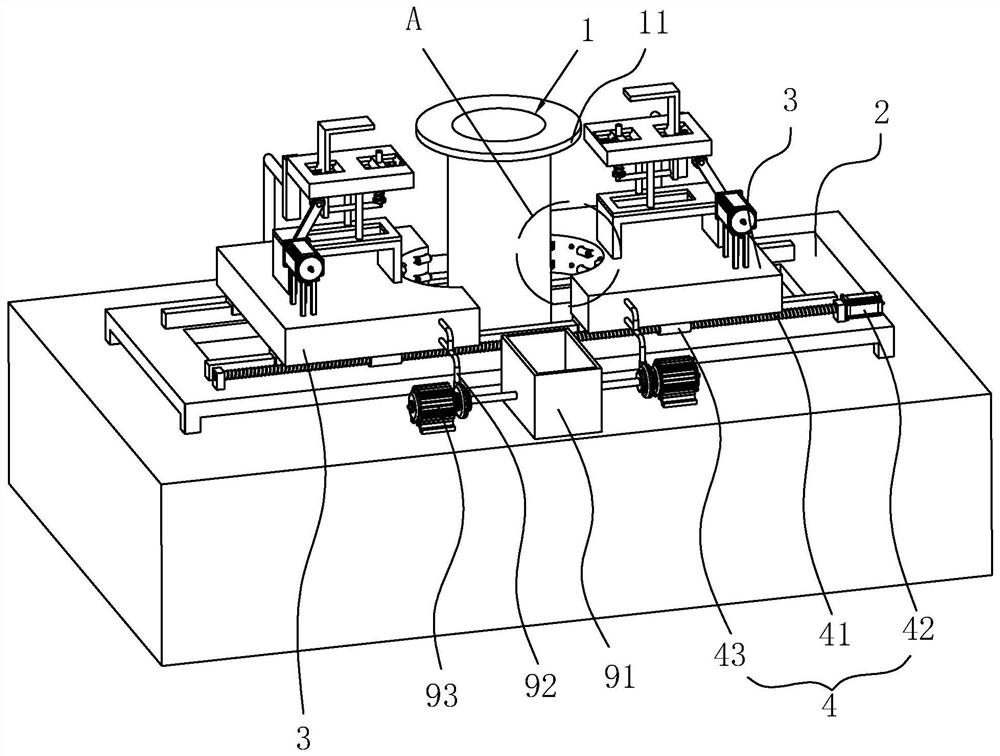
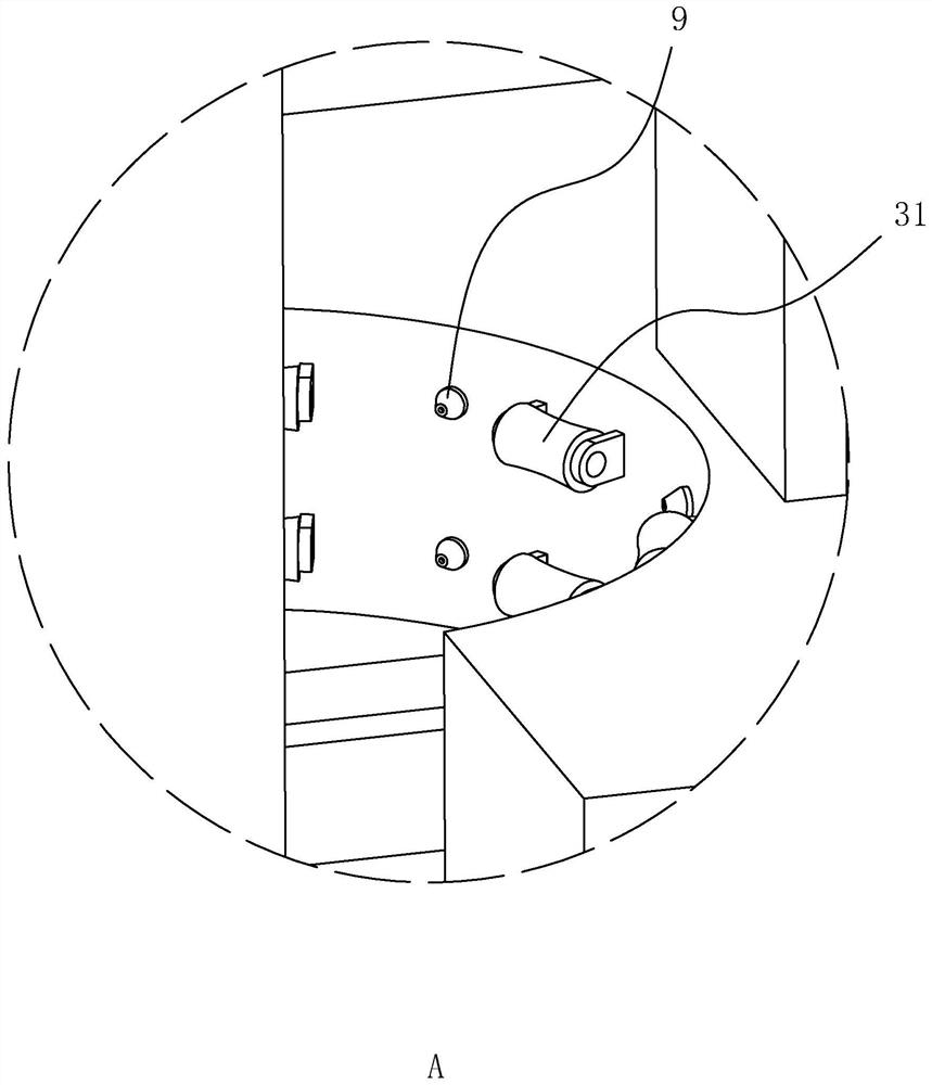
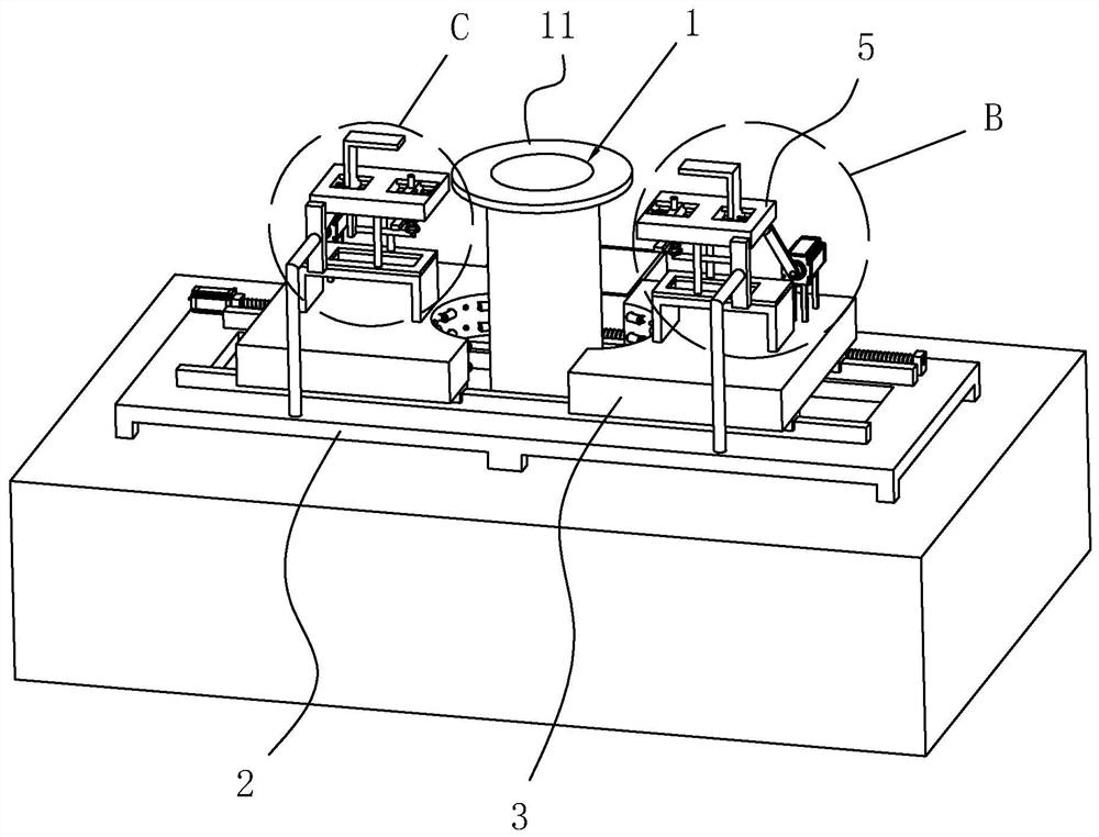
[0041] The following is attached Figure 1-5 The application is described in further detail.

[0042] The embodiment of the present application discloses a grouting device for bored piles. refer to figure 1 , including a frame 2 and two sliding seats 3, the frame 2 is placed on the ground at the position of the hole 1 of the foundation pile, the middle part of the frame 2 is hollowed out, and the hole 1 of the foundation pile is aligned with the hollowed out position of the middle part of the frame 2. On the top wall of the frame 2, guide rails are respectively bolt-fixed on the two side edges in the length direction of the frame 2, and the two sliding seats 3 are all slidably installed on the guide rails. The two sliding seats 3 are respectively located on both sides of the hole 1 of the foundation pile on the frame 2 , the sliding directions of the two sliding seats 3 are on a straight line, and they move symmetrically and reversely on both sides of the hole 1 .

[0043] ...


PUM


Abstract

The invention relates to a cast-in-situ bored pile grouting device and a construction method thereof. The cast-in-situ bored pile grouting device comprises a rack arranged at an orifice of a foundation pile, two sliding seats symmetrically sliding in the radial direction of the orifice on the rack, guide rollers rotationally arranged on the side walls, close to the orifice, of the sliding seats, and a driving device for driving the two sliding seats to synchronously and reversely slide are arranged on the rack; the cast-in-situ bored pile grouting device further comprises lap-joint lugs whichare fixedly connected to the outer walls of the two ends of a pipe section, a lap-joint table is arranged on the sliding seats in a lifting mode in the vertical direction, and a lifting device used for driving the lap-joint table to ascend and descend in a reciprocating mode is arranged on the sliding seats; and when concrete is poured, the spliced pipe section is inserted into the orifice, the two sliding seats are driven to synchronously get close to each other and clamp a grouting pipe, the guide rollers play a role in guiding and correcting the grouting pipe, then the lap-joint lugs on thegrouting pipe are in lap joint with the lap-joint table, then the lap-joint table is driven to ascend and descend up and down in a reciprocating mode, and smooth flowing of the concrete in the grouting pipe is guaranteed. The cast-in-situ bored pile grouting device and the construction method thereof have the effects of improving the quality of the foundation pile and saving manpower.

Description

technical field [0001] The present application relates to the field of foundation pile construction engineering, in particular to a bored pile grouting device and a construction method thereof. Background technique [0002] Bored cast-in-situ pile refers to the pile hole formed in the foundation soil by means of mechanical drilling, steel pipe extrusion or manual excavation on the project site, and a steel cage is placed in it and concrete is poured into it. Compared with the hammering method in sinking piles, the construction noise and vibration are much smaller, piles much larger in diameter than prefabricated piles can be built, and it can be used on various foundations. [0003] The patent with the authorized notification number CN207775893U discloses a sectioned grouting pipe for bored pile foundation, including: a plurality of pipe sections spliced ​​and connected to each other, and a joint is set on the lower pipe section of the two adjacent pipe sections. A partitio...

Claims


Application Information

Patent Timeline
Patent Type & Authority Applications(China)
IPC IPC(8): E02D15/04E02D5/38
CPCE02D5/38E02D15/04E02D2250/003
Inventor 李伟杨红法钟曙光孙万军郑青青
Owner 飞帆集团有限公司
Learn More