Cantilever steel beam system scaffold moving positioning pile and construction method

A mobile positioning and scaffolding technology, which is applied to the accessories of scaffolding, the scaffolding supported by the building structure, the support of the building structure, etc., can solve the problems of labor and time, save costs, improve construction efficiency and construction accuracy requirements, and ensure construction safety. Effect

Pending Publication Date: 2021-01-15
CHINA CONSTR FIRST DIV GROUP CONSTR & DEV
View PDF0 Cites 1 Cited by
  • Summary
  • Abstract
  • Description
  • Claims
  • Application Information

AI Technical Summary

Problems solved by technology

In order to prevent the displacement of the scaffolding pole during the erection of conventional cantilevered steel beam scaffolding, it is necessary to weld a small section of steel bar head on the upper part of the cantilevered steel beam to fix the scaffolding pole on the steel beam. When the horizontal distance is different from the previous one, it needs to be cut and re-welded, which is labor-intensive and time-consuming

Method used


Image

  • Cantilever steel beam system scaffold moving positioning pile and construction method
  • Cantilever steel beam system scaffold moving positioning pile and construction method

Examples


Embodiment 1

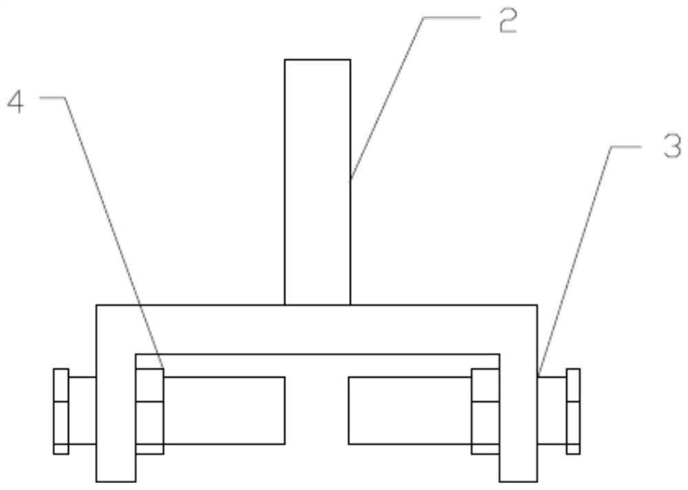
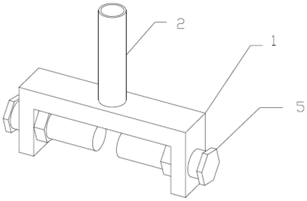
[0028] combined with figure 1 and 2 , a mobile positioning pile for scaffolding of a cantilevered steel beam system, comprising an inverted U-shaped base 1, a connecting pipe 2 is fixedly connected to the upper part of the base 1, bolt holes 3 are arranged on both sides of the base 1, and the central axes of the bolt holes 3 are collinear A nut 4 is fixedly connected to the inner surface of the base 1 and corresponding to the position of the bolt hole 3, and the inner diameter of the nut 4 is smaller than the inner diameter of the bolt hole 3; a bolt 5 is pierced in the bolt hole 3, and the bolt 5 and the nut 4 are screwed together ; The length of the bolt 5 is greater than half of the width of the base 1 .

[0029] The connecting pipe 2 is located at the center of the upper part of the base 1, and the connecting pipe 2 is fully welded on the base 1 along its circumferential direction.

[0030] The inner diameter of the bolt hole 3 is larger than the inner diameter of the nu...

Embodiment 2

[0032] In the present embodiment, the method of using the positioning piles in the first embodiment to carry out construction is proposed:

[0033] S1. Erection of cantilevered steel beams:

[0034] According to the requirements of the floor plan in the construction plan, the line is measured and set out, and the anchor rings are drilled and pre-embedded at the corresponding positions of the steel beams. The distance between the anchor rings is the same as the content of the plan; Ensure that the tightening torque of the nut at the anchorage end meets the requirements of the plan, the distance between the cantilevered steel beam and the anchor ring has been plugged tightly with wooden squares, and the next step can only be carried out after the construction of the cantilevered steel beam has passed the acceptance;

[0035] S2. Place the positioning pile:

[0036] Loosen the bolts on both sides of the positioning pile in advance, and then insert the positioning pile from the e...


PUM


Abstract

The invention discloses a cantilever steel beam system scaffold moving positioning pile. The scaffold moving positioning pile comprises an inverted-U-shaped base, a connecting pipe is fixedly connected to the upper portion of the base, bolt holes are formed in the two sides of the base, the central axes of the bolt holes are collinear, nuts are fixedly connected to the positions, corresponding tothe bolt holes, of the inner side faces of the base, the inner diameter of the nuts is smaller than that of the bolt holes, bolts are arranged in the bolt holes in a penetrating mode and connected with the nuts in a threaded mode, and the length of the bolts is larger than half of the width of the base. The invention further provides a construction method of the positioning pile. By adopting the positioning pile and the construction method for construction, the purpose of shortening the construction period is achieved, and the positioning pile can be widely applied to the technical field of cantilever steel beam scaffold construction.

Description

technical field [0001] The invention relates to the construction field of cantilevered steel beam scaffolding, in particular to a mobile positioning pile and a construction method of a cantilevered steel beam system scaffolding. Background technique [0002] At present, the use of cantilevered steel beam scaffolding construction system for high-rise buildings and small high-rise buildings in domestic construction is a very common and common construction method. Cantilevered steel beam scaffolding has the advantages of local materials, convenient erection, safety and reliability, Cost savings and many other advantages, while the effect of the outer frame facade is the first business card of construction management, and the first expression of the construction corporate culture. In order to prevent the displacement of the scaffolding pole during the erection of conventional cantilevered steel beam scaffolding, it is necessary to weld a small section of steel bar head on the up...

Claims


Application Information

Patent Timeline
IPC IPC(8): E04G3/18E04G5/00
CPCE04G3/18E04G5/00
Inventor 周立龙王春阳赵海岩李志朋郎小伟王小兵梅砚博刘明威苗昱明夏海雁
Owner CHINA CONSTR FIRST DIV GROUP CONSTR & DEV
Why Eureka
Try Eureka