Drying equipment for bioengineering based on environmental protection

A bioengineering and drying equipment technology, applied in the direction of drying solid materials, dry goods handling, drying chamber/container, etc., can solve the problems of incomplete drying of items, low work efficiency, slow drying speed, etc., to save manpower and improve work The effect of quality, convenient collection

Active Publication Date: 2021-01-15
广州市粤家科技发展有限公司
View PDF4 Cites 1 Cited by
  • Summary
  • Abstract
  • Description
  • Claims
  • Application Information

AI Technical Summary

Problems solved by technology

[0005] In order to overcome the shortcomings of slow drying speed, incomplete drying of items, manual collection after drying, and low work efficiency, the technical problem to be solved is:

Method used


Image

  • Drying equipment for bioengineering based on environmental protection
  • Drying equipment for bioengineering based on environmental protection
  • Drying equipment for bioengineering based on environmental protection

Examples


Embodiment 1

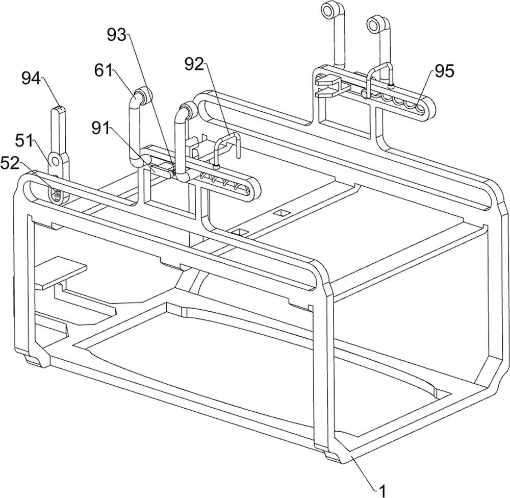
[0026] A kind of drying equipment for bioengineering based on environmental protection, such as figure 1 As shown, it includes a frame 1, a circular shaft 2, a connecting rod 3, a drive assembly 4, a placement assembly 5 and a drying assembly 6. The circular shaft 2 is slidingly provided on the frame 1, and the bottom of the circular shaft 2 is equipped with a connecting rod. 3. The frame 1 is provided with a driving assembly 4 driven by rotation, the frame 1 is provided with a placement assembly 5, and the frame 1 is provided with a drying assembly 6 for drying by sliding.

[0027] When using the device, first place the items to be dried through the placement component 5, then push the placement component 5 to move to the right through the drive component 4, and at the same time dry the items through the drying component 6. After completion, place the dried items Take it out, then control the drive assembly 4 to drive the placement assembly 5 to reset, and close the drive ass...

Embodiment 2

[0035] On the basis of Example 1, such as figure 1 and Figure 5 As shown, it also includes a pouring assembly 7, and the pouring assembly 7 includes a rack 71 and a full gear 72. The front and rear two parts on the right side of the frame 1 are provided with a rack 71, and the front and rear sides of the placement frame 53 are provided with full gears. The gear 72, the rack 71 meshes with the full gear 72.

[0036] When the article is dried, the placement frame 53 drives the full gear 72 to move to the right, and when the full gear 72 moves to the right to mesh with the rack 71, the full gear 72 rotates to drive the placement frame 53 to rotate downwards to pour the article out, completing Finally, the placement frame 53 drives the full gear 72 to move to the left and reset, and at the same time, under the action of the rack 71, the full gear 72 moves to the left and resets to drive the placement frame 53 to rotate upwards to reset, so that the article can be poured out auto...


PUM


Abstract

The invention relates to drying equipment, in particular to drying equipment for bioengineering based on environmental protection. The invention provides drying equipment for bioengineering based on environmental protection, which is high in drying speed and comprehensive in article drying, and manual collection is not needed after drying is completed. The drying equipment for bioengineering basedon environmental protection comprises a rack, a circular shaft, two connecting rods, a driving assembly, a placing assembly and a drying assembly, wherein the circular shaft is mounted on the rack ina sliding manner; two connecting rods both are mounted on the circular shaft; the driving assembly is mounted on the rack and carries out drying in a rotating manner; the placing assembly is mountedon the rack; and the drying assembly is mounted on the rack. According to the drying equipment, articles in the placing assembly can be heated more evenly when dried through the driving assembly, thearticles can be placed through the placing assembly to be dried conveniently, the articles in a placing frame can be dried quickly through the drying assembly, and the articles can be automatically poured out through cooperation of racks and full gears, so that people can collect the articles more conveniently.

Description

technical field [0001] The invention relates to a drying device, in particular to a drying device for bioengineering based on environmental protection. Background technique [0002] The existing microbiology-based industry relies on genetic engineering and utilization to improve, and at the same time alleviate the problem of environmental pollution. Structurally complex but regenerative substrates like lignocellulose will become feedstock for the fermentation industry and likely also provide starting ingredients for the plastics and polymer industries. [0003] Before cultivating the items, the items need to be dried. At present, the drying speed of the existing drying equipment is slow, and the drying of the cell engineering is not comprehensive. After the drying is completed, it needs to be collected manually, which reduces the work efficiency. [0004] Therefore, it is necessary to invent a kind of drying equipment based on environmental protection, which is fast in dryi...

Claims


Application Information

Patent Timeline
IPC IPC(8): F26B11/00F26B25/00F26B25/02F26B25/18F26B23/00
CPCF26B11/00F26B23/00F26B25/002F26B25/02F26B25/18
Inventor 李鲜艳
Owner 广州市粤家科技发展有限公司
Why Eureka
Try Eureka