Space-time synchronization system and device for laser radar and camera data and readable medium

A laser radar and synchronization system technology, applied to the time synchronization and space alignment of the two sensors of the camera, in the field of vehicle laser radar, can solve the problem of low precision, unsatisfactory automatic driving, time synchronization accuracy and system reliability. Automated driving needs and other issues to achieve the effect of improving consistency

Pending Publication Date: 2021-01-15
深兰人工智能(深圳)有限公司
View PDF0 Cites 17 Cited by
  • Summary
  • Abstract
  • Description
  • Claims
  • Application Information

AI Technical Summary

Problems solved by technology

The multi-sensor time synchronization method and system for UAV power inspection in the prior art uses the ARM system to detect and process PPS pulses, which has poor real-time performance and low precision
Does not meet the needs of the field of autonomous driving
[0003] The multi-channel high-speed pulse input time synchronization equipment in the prior art uses MCU as the pulse detection and processing equipment, and at the same time converts RS232 to the network port. The time synchronization accuracy and system reliability do not meet the requirements of automatic driving.

Method used


Image

  • Space-time synchronization system and device for laser radar and camera data and readable medium
  • Space-time synchronization system and device for laser radar and camera data and readable medium
  • Space-time synchronization system and device for laser radar and camera data and readable medium

Examples


Embodiment

[0053] In order to solve the technical problems in the aforementioned background technology, the method for controlling the virtual reality object will be introduced in detail below.

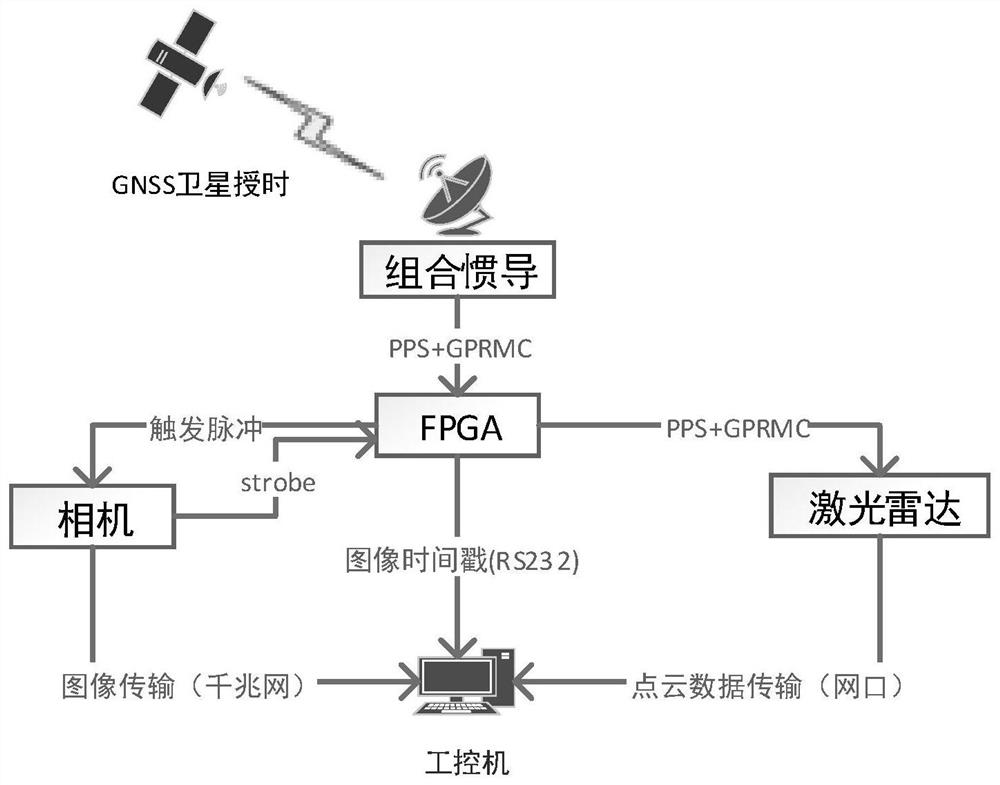
[0054] The time and space synchronization scheme of FPGA-based self-driving lidar and camera according to the present invention, its hardware core is as follows: figure 1 As shown, it includes: FPGA module, industrial computer, sensor module includes: combined inertial navigation module, laser radar, camera, etc. Such as Figure 4 It is a flowchart of the present invention.

[0055] S100, FPGA receives external timing, combines the PPS second pulse + GPRMC message generated by the inertial navigation module, and corrects the local clock; even when the GNSS signal is blocked, the FPGA can still maintain the clock accuracy for a certain period of time by its own crystal oscillator;

[0056] S200. The FPGA sends a PPS second pulse + GPRMC message to the laser radar, so that the internal clock sys...


PUM


Abstract

The invention discloses a space-time synchronization system for laser radar and camera data. The space-time synchronization system comprises an FPGA local clock correction module, an FPGA, a laser radar synchronization module, an FPGA triggering camera module which sends a picture of the camera containing the internal timestamp of the camera to an industrial personal computer; a camera picture timestamp module which is used for receiving flash lamp pulses generated during camera exposure by the FPGA and marking timestamps under an FPGA clock system for exposure moments of camera pictures; a timestamp matching module which is used for triggering the camera pictures with the camera internal timestamps sent by the camera module by the FPGA and receiving the camera pictures with the timestampsunder the FPGA clock system sent by the FPGA for matching; and a point cloud data compensation and fusion module which compensates the point cloud to the position of the exposure moment of the camera; and according to the measured external parameters of the laser radar and the camera, carries out alignment fusion on the point cloud data and the camera picture. Synchronous acquisition of the camera and the laser radar is realized.

Description

technical field [0001] The invention relates to the technical field of automatic driving, in particular to a method for time synchronization and spatial alignment of two sensors of a vehicle laser radar and a camera. Background technique [0002] The current autonomous driving system includes modules such as perception, positioning, decision planning, and control. The normal operation of these modules depends on the accurate fusion of various types of sensor data. In particular, the two sensors of lidar and camera play a vital role in the perception and positioning module. The mechanical rotary scanning lidar itself has a low scanning frequency, and the vehicle often runs at high speed and high maneuverability, causing motion distortion in the point cloud measured by the lidar. In the fusion process of lidar and camera pictures, there will also be a certain measurement deviation caused by asynchronous data collection, and this deviation will be amplified as the speed of the...

Claims


Application Information

Patent Timeline
Patent Type & Authority Applications(China)
IPC IPC(8): G01S17/86G01S17/931G01S7/497
CPCG01S7/497G01S17/86G01S17/931
Inventor 陈海波吴在刚周源思张保群
Owner 深兰人工智能(深圳)有限公司
Why Eureka
Try Eureka