Dual-polarized transmissive surface with controlled electrical characteristics and its design method with filter circuit terminated
A filter circuit and transmission surface technology, applied in the field of dual-polarization transmission surface and its design, can solve the problems of poor frequency selection ability, difficulty in realizing two polarizations with different transmission frequency bands, and inability to obtain out-of-band suppression effect, etc., to achieve Effect of increasing degrees of freedom, steep out-of-band suppression characteristics
- Summary
- Abstract
- Description
- Claims
- Application Information
AI Technical Summary
Problems solved by technology
Method used
Image
Examples
Embodiment
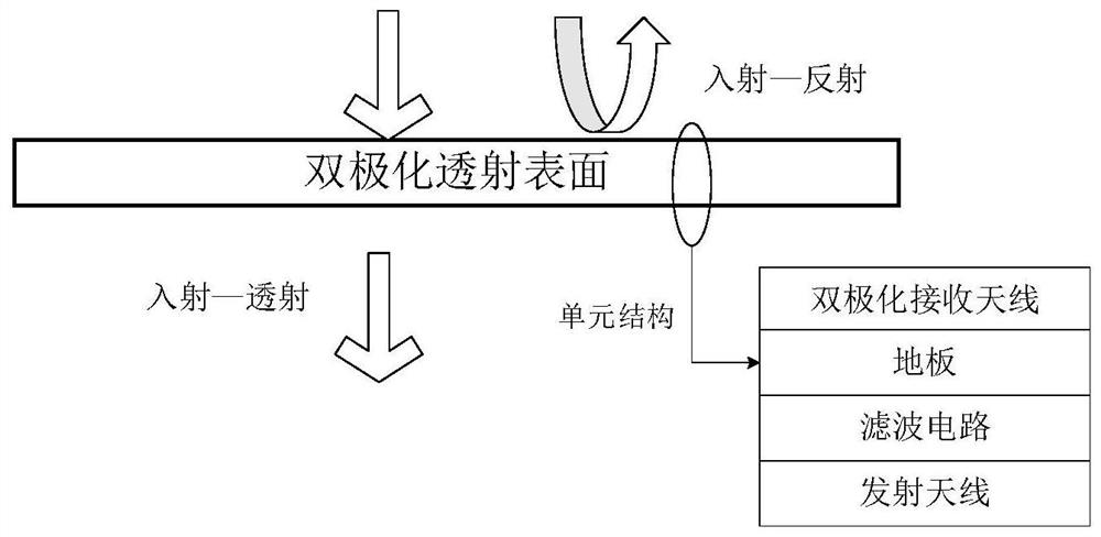
[0062] In this embodiment, a dual-polarized transmissive surface that is terminated with a filter circuit to control electrical characteristics is taken as an example. The TM polarization (the electric field direction of the incident wave is along the y-axis) of the transmissive surface has a transmission frequency band, a reflection frequency band, and TE polarization (incident wave) The electric field direction of the wave along the x-axis) has a transmission band different from the range of the TM polarization transmission band. The transmissive surface in this embodiment can be used as a dichroic mirror for the sub-reflector of the Cassegrain antenna. Below we further describe in detail in conjunction with the accompanying drawings.
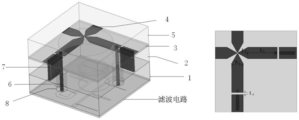
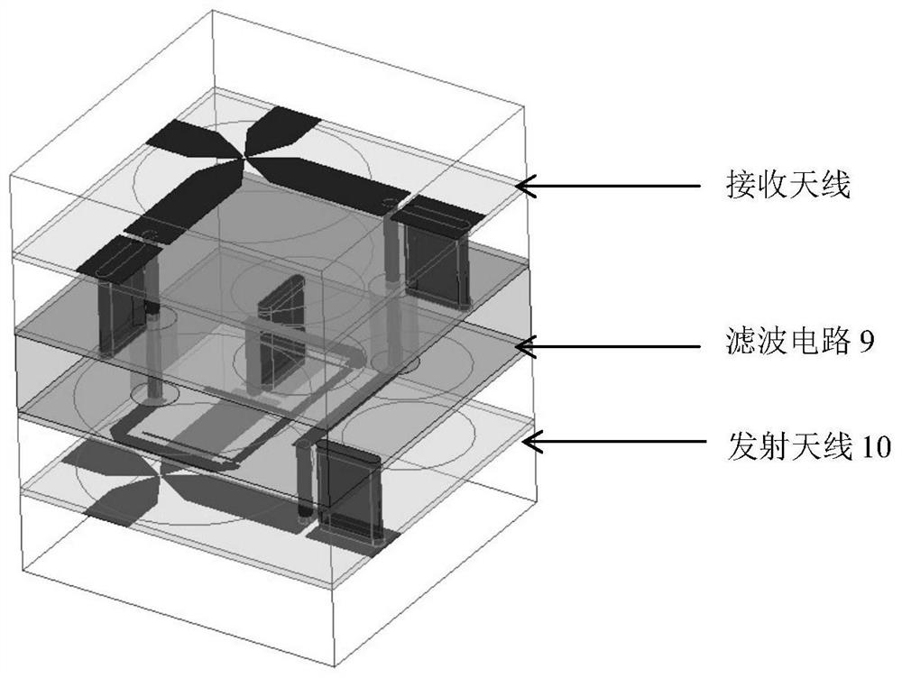
[0063] see figure 1 , is a schematic diagram of a dual-polarized transmissive surface realized by using a termination filter circuit in this embodiment. The transmissive surface includes a tightly coupled dual-polarized dipole receiving ant...
PUM
 Abstract
Description
Claims
Application Information
 - R&D
- Intellectual Property
- Life Sciences
- Materials
- Tech Scout
- Unparalleled Data Quality
- Higher Quality Content
- 60% Fewer Hallucinations
Browse by: Latest US Patents, China's latest patents, Technical Efficacy Thesaurus, Application Domain, Technology Topic, Popular Technical Reports.
© 2025 PatSnap. All rights reserved.Legal|Privacy policy|Modern Slavery Act Transparency Statement|Sitemap|About US| Contact US: help@patsnap.com


