
A terahertz frequency sweep system

A terahertz and frequency sweep technology, applied in the field of terahertz light sources, can solve problems such as limited resolution, sample damage, and high peak power, and achieve the effects of high frequency sweep rate, good stability, and wide sweep bandwidth

Active Publication Date: 2022-02-18
HUAZHONG UNIV OF SCI & TECH
View PDF8 Cites 0 Cited by
  • Summary
  • Abstract
  • Description
  • Claims
  • Application Information

AI Technical Summary

Problems solved by technology

[0003] In the early stage of terahertz measurement, it mainly relied on time-domain terahertz spectrometer. Using femtosecond pulse with high peak power to generate terahertz signal is the main way. It has the advantages of large bandwidth and measurement rate in the order of Hz to kHz, but it is an ultrashort pulse Type terahertz, limited resolution, high peak power, damage to some samples

Method used


Image

  • A terahertz frequency sweep system
  • A terahertz frequency sweep system
  • A terahertz frequency sweep system

Examples


Embodiment Construction

[0058] In order to make the object, technical solution and advantages of the present invention clearer, the present invention will be further described in detail below in conjunction with the accompanying drawings and embodiments. It should be understood that the specific embodiments described here are only used to explain the present invention, not to limit the present invention. In addition, the technical features involved in the various embodiments of the present invention described below can be combined with each other as long as they do not constitute a conflict with each other.

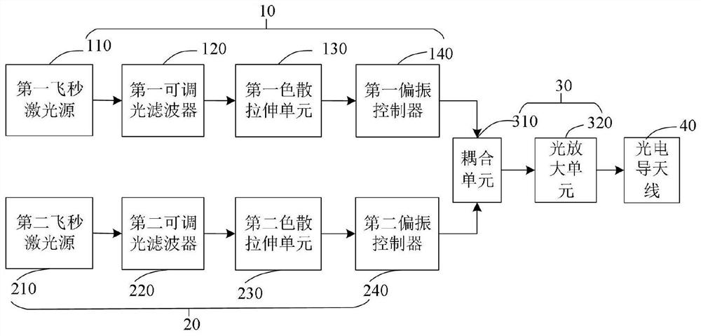
[0059] figure 1 It is a schematic structural diagram of a terahertz frequency sweep source in an embodiment of the present application. like figure 1 As shown, the terahertz frequency sweep source includes: a first optical frequency comb generation module 10, which is used to periodically emit the first original optical frequency comb of the first repetition frequency, and stretch the first or...


PUM


Abstract

The invention discloses a terahertz frequency sweep source and system, in the field of terahertz light sources, the terahertz frequency sweep source includes: a first optical frequency comb generation module, which is used to periodically emit the first original optical frequency comb of the first repetition frequency , and stretch the first original optical frequency comb into a first output optical frequency comb with a width of ns order of magnitude; the second optical frequency comb generation module is used to emit a second frequency comb with a center wavelength and a second repetition frequency with controllable bandwidth The original optical frequency comb, and stretching the second original optical frequency comb into a second output optical frequency comb with a width of ns order of magnitude, there is a repetition frequency difference between the first repetition frequency and the second repetition frequency; the coupling amplification module is used to The received first output optical frequency comb and the second output optical frequency comb perform power coupling to generate a light intensity signal at a terahertz frequency; the photoconductive antenna is used to convert the light intensity signal into a terahertz signal and emit it. In this application, a terahertz frequency scanning source with wide scanning bandwidth, high frequency scanning rate and high linearity is generated by optical beat frequency after dispersion stretching by optical fiber dual frequency comb.

Description

technical field [0001] The invention belongs to the field of terahertz light sources, in particular to a pulsed terahertz source, and more specifically to a terahertz frequency sweep source and system. Background technique [0002] Terahertz waves are electromagnetic waves with frequencies ranging from 0.1THz to 10THz, corresponding to electromagnetic wavelengths ranging from 3mm to 30μm, located between microwave and optical bands, and have unique properties: transient, broadband, low-energy, penetrating, Absorbency, fingerprint properties, etc. These properties make terahertz have great potential in wireless communication, security detection and anti-terrorism, material analysis and other fields, especially terahertz technology is vigorously promoting industrial applications. [0003] In the early stage of terahertz measurement, it mainly relied on time-domain terahertz spectrometer. Using femtosecond pulse with high peak power to generate terahertz signal is the main way...

Claims


Application Information

Patent Timeline
Patent Type & Authority Patents(China)
IPC IPC(8): H04B10/50H04B10/60H04B10/90G01N21/3581
CPCH04B10/90H04B10/501H04B10/60G01N21/3581
Inventor 张新亮陈燎张驰王若兰
Owner HUAZHONG UNIV OF SCI & TECH
Learn More