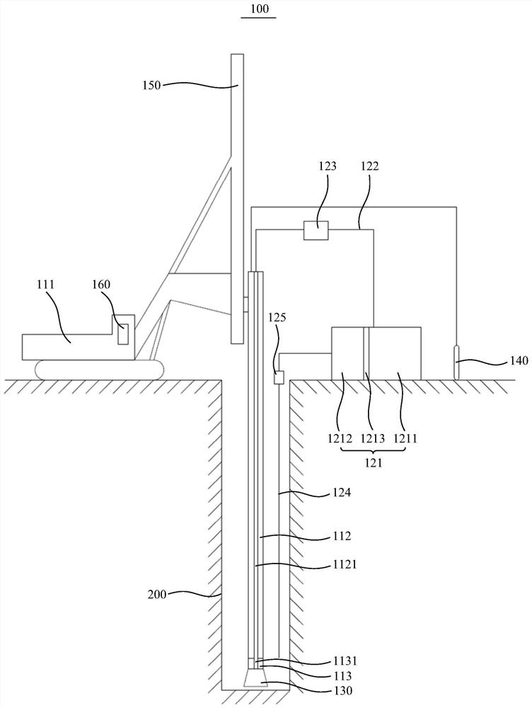
Plasma pulse rock breaking pile machine

A plasma and pulse technology, which is applied in the field of plasma pulse rock breaking pile machine, can solve the problems of complex structure, low work efficiency, and inability to adapt to rock formations with different hardness.

Pending Publication Date: 2021-01-19
BEIJING SANY INTELLIGENT MFG TECH CO LTD
View PDF0 Cites 1 Cited by
  • Summary
  • Abstract
  • Description
  • Claims
  • Application Information

AI Technical Summary

Problems solved by technology

[0005] The purpose of the present invention is to provide a plasma pulse rock breaking machine to solve the technical problems in the prior

Method used


Image

  • Plasma pulse rock breaking pile machine

Examples


Embodiment Construction

[0022] In order to make the purpose, technical solutions and advantages of the embodiments of the present invention clearer, the technical solutions in the embodiments of the present invention will be clearly and completely described below in conjunction with the drawings in the embodiments of the present invention. Obviously, the described embodiments It is a part of embodiments of the present invention, but not all embodiments. The components of the embodiments of the invention generally described and illustrated in the figures herein may be arranged and designed in a variety of different configurations. Accordingly, the following detailed description of the embodiments of the invention provided in the accompanying drawings is not intended to limit the scope of the claimed invention, but merely represents selected embodiments of the invention. Based on the embodiments of the present invention, all other embodiments obtained by persons of ordinary skill in the art without cre...


PUM


Abstract

The invention discloses a plasma pulse rock breaking pile machine, and relates to the technical field of pile foundation construction. The plasma pulse rock breaking pile machine comprises a pulse discharging mechanism, a circulating mechanism and a drill bit connected with the pulse discharging mechanism, wherein the pulse discharging mechanism outputs high-voltage pulses to the drill bit to enable the drill bit to generate high-voltage arcs, and the circulating mechanism is used for conveying electrolyte to the drill bit and pumping mud generated by drilling out of a pile foundation. The plasma pulse rock breaking pile machine is based on a plasma rock breaking technology, rock breaking is achieved through arc energy through cooperation of the pulse discharging mechanism and the drill bit, and compared with mechanical rock breaking in the prior art, the plasma pulse rock breaking pile machine is simple in structure, capable of achieving the purpose of rapid pile driving and hole forming, and has the advantages of being small in mechanical abrasion, high in working efficiency, and adaptive to rock strata with different hardness.

Description

technical field [0001] The invention relates to the technical field of pile foundation construction, in particular to a plasma pulse rock breaking pile machine. Background technique [0002] Traditional pile foundation construction basically uses rotary drilling rigs, electro-hydraulic pile drivers, impact vibrating hammers, etc. for mechanical rock breaking or manual drilling. When drilling soft rock and medium-hard rock formations, rotary drill bits with cemented carbide cutters are usually used for drilling; when drilling medium-hard rock formations and above, milling tooth roller cone bits are usually used for drilling; When drilling into rock, diamond drill bits or steel grain drill bits are usually used for drilling; while for hard and brittle rock formations, hydraulic (pneumatic) in-hole impactors or insert drill bits are usually used for drilling. [0003] The rock drilling equipment in the prior art has a complex mechanical structure, low working efficiency, and c...

Claims


Application Information

Patent Timeline
IPC IPC(8): E21B7/02E21B7/04E21B7/15E21B12/00E21B21/00
CPCE21B7/02E21B7/04E21B7/15E21B12/00E21B21/00
Inventor 周鹏马宁黄雪
Owner BEIJING SANY INTELLIGENT MFG TECH CO LTD
Why Eureka
Try Eureka