Optical tweezer magnetic levitation observation device

An observation device and magnetic levitation technology, applied in the field of optical tweezers, can solve the problems of complex optical tweezers structure and inconvenient observation, and achieve the effects of convenient heat dissipation, convenient installation and support, and reduced failure rate

Inactive Publication Date: 2021-01-19
漳州市龙文区健达电子科技有限公司
View PDF0 Cites 0 Cited by
  • Summary
  • Abstract
  • Description
  • Claims
  • Application Information

AI Technical Summary

Problems solved by technology

[0002] Optical tweezers are optical traps using chip-based photon resonance capture technology, which can manipulate and capture nanometer to micron-scale examples. Optical traps can be formed by laser aggregation, and tiny objects are trapped in optical traps by light pressure. Moving the light beam makes tiny objects move with the optical trap, so that tiny objects, such as viruses, bacteria, and intracellular organelles and cellular components, can be displaced or operated under a microscope. Optical tweezers that capture tiny particles are a A special light field, when this light field interacts with an object, the entire object is affected by the light to achieve the effect of being clamped, and then the object can be moved by moving the light beam. The existing optical tweezers have complex structures and are inconvenient to perform Observed

Method used


Image

  • Optical tweezer magnetic levitation observation device
  • Optical tweezer magnetic levitation observation device
  • Optical tweezer magnetic levitation observation device

Examples


Embodiment approach

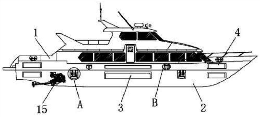
[0022] As a preferred embodiment of the present invention, the bottom of the main body 1 is symmetrically equipped with a support plate 2, the shape of the support plate 2 is "L", and the bottom of the support plate 2 is provided with anti-slip lines to improve the device stability.

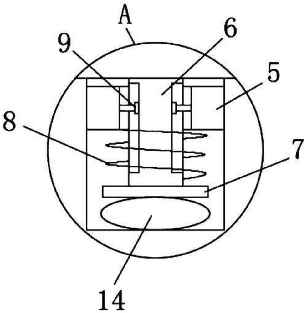
[0023] As a preferred embodiment of the present invention, a metal shielding layer 15 is provided on the inner wall of the installation groove 13, and a metal shielding layer 15 is provided between the eyepiece 8 and the suspension block coil 18, which can improve the performance of the eyepiece 8 and the microscope. The accuracy of the digital camera 10 is prevented from affecting the use of the eyepiece 8 and the microscopic digital camera 10.

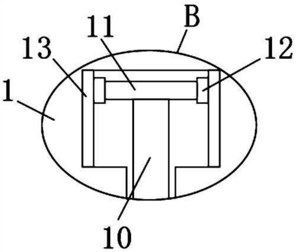
[0024] As a preferred embodiment of the present invention, both sides of the main body 1 are symmetrically provided with ventilation openings 12, and one side of the installation groove 13 is provided with cooling holes 16 to facilitate heat dissipation...


PUM


Abstract

The invention provides an optical tweezers magnetic levitation observation device which comprises a main body, a supporting plate, a support, a laser generator, a placement frame, a levitation block,a microscopic digital camera and a display screen, a through hole is formed in the center of the main body, a mounting groove is formed in the main body, and a main body coil is fixedly mounted in themounting groove; a support is welded to one side of the top of the main body. According to the optical tweezer magnetic levitation observation device, the magnitude of current in the main body coil can be controlled through the controller, so that the magnetic field intensity of the main body coil is controlled, the height of the levitation block can be adjusted, and the position of a formed optical trap is adjusted through the eyepiece; bacteria or microorganisms can suspend, the suspension block can be conveniently installed and supported through the containing frame, the suspended bacteriaand microorganisms can be conveniently observed through the microscopic digital camera and the display screen, heat dissipation is conveniently conducted on the main body coil through the ventilationopenings and the heat dissipation holes, and the failure rate is reduced.

Description

technical field [0001] The invention relates to the technical field of optical tweezers, in particular to an optical tweezers magnetic levitation observation device. Background technique [0002] Optical tweezers are optical traps using chip-based photon resonance capture technology, which can manipulate and capture nanometer to micron-scale examples. Optical traps can be formed by laser aggregation, and tiny objects are trapped in optical traps by light pressure. Moving the light beam makes tiny objects move with the optical trap, so that tiny objects, such as viruses, bacteria, and intracellular organelles and cellular components, can be displaced or operated under a microscope. Optical tweezers that capture tiny particles are a A special light field, when this light field interacts with an object, the entire object is affected by the light to achieve the effect of being clamped, and then the object can be moved by moving the light beam. The existing optical tweezers have ...

Claims


Application Information

Patent Timeline
Patent Type & Authority Applications(China)
IPC IPC(8): G02B21/28G02B21/32G02B21/36
CPCG02B21/28G02B21/32G02B21/365G02B21/368
Inventor 林建铃
Owner 漳州市龙文区健达电子科技有限公司
Why Eureka
Try Eureka