Forage smashing device for animal husbandry

A crushing device and fodder technology, which is applied in application, feed, transportation and packaging, etc., can solve the problems of poor crushing effect, unfavorable forage and other feed ingredients fully mixed, and inability to remove dust, etc.

Active Publication Date: 2021-01-22
湖南德人牧业科技有限公司 +1
View PDF9 Cites 1 Cited by
  • Summary
  • Abstract
  • Description
  • Claims
  • Application Information

AI Technical Summary

Problems solved by technology

[0004] In order to overcome the shortcomings of the existing forage crushing device that cannot adjust the crushing length of forage, cannot remove dust, and has poor crushing effect, which is not conducive to the thorough mixing of forage and other feed ingredients, the technical problem to be solved is: provide an adjustable forage Hay shredding device for animal husbandry with shredding length, dedusting of hay, and easy mixing with other feeds

Method used


Image

  • Forage smashing device for animal husbandry
  • Forage smashing device for animal husbandry
  • Forage smashing device for animal husbandry

Examples


Embodiment 1

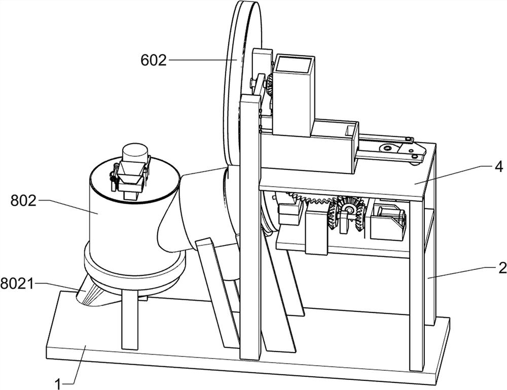
[0027] A kind of forage crushing device for animal husbandry, such as figure 1As shown, it includes the bottom plate 1, the outriggers 2, the horizontal plate 3, the gear device, the first frame 301, the machine sleeve 305, the convex plate 4, the feeding device, the inclined plate 5, the long leg 6, the horizontal bar 601, the cutting device , the second support rod 7, the short rod 8 and the circle 801, the bottom plate 1 is fixedly installed with the outrigger 2, the inclined plate 5, the long leg 6, the second support rod 7 and the short rod 8, among which the outrigger 2, the inclined plate 5 , The long leg 6, the second support rod 7 and the short rod 8 are each provided with two symmetrically front and rear, the leg 2 is installed on the far right of the bottom plate 1, the short rod 8 is installed on the left side of the bottom plate 1, the inclined plate 5, the long leg 6, The second strut 7 is installed in the middle of the bottom plate 1, and the inclined plate 5, t...

Embodiment 2

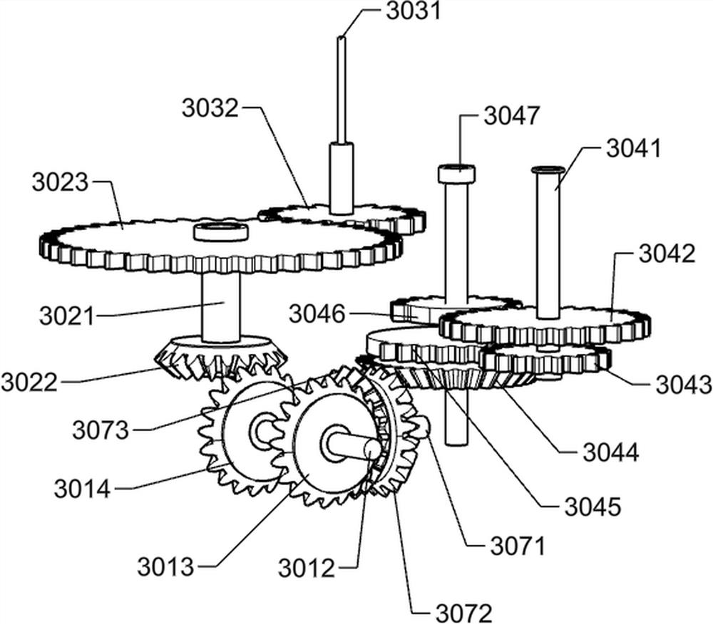
[0030] On the basis of Example 1, as Figure 2-6 As shown, the gear device includes a first motor 3011, a first shaft 3012, a first gear 3013, a second gear 3014, a first T-frame 302, a second shaft 3021, a third gear 3022, a fourth gear 3023, a second T-frame 303, third shaft 3031, fifth gear 3032, third T-frame 304, fourth shaft 3041, sixth gear 3042, seventh gear 3043, eighth gear 3044, ninth gear 3045, tenth gear 3046, The fifth shaft 3047, the first strut 306, the support plate 307, the sixth shaft 3071, the eleventh gear 3072 and the twelfth gear 3073, the horizontal plate 3 is fixedly connected with the first frame 301 and the first T frame 302 , the second T frame 303, the third T frame 304, the first strut 306 and the support plate 307, wherein the first T frame 302 is located on the left front side of the horizontal plate 3, and the first frame 301 is located on the upper right side of the horizontal plate 3, The first support rod 306 is located on the left side of ...

Embodiment 3

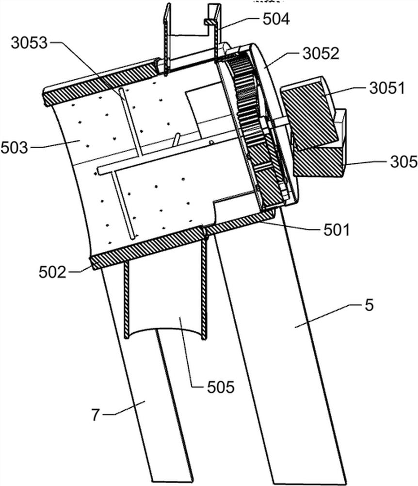
[0039] On the basis of Example 2, as Figure 7-9 As shown, it also includes a round sleeve 501, a sliding barrel 502, a hole barrel 503, a feeding channel 504, a waste barrel 505, a second motor 3051, a planetary gear set 3052 and a stirring rod 3053, and the round sleeve 501 is fixedly connected to the swash plate 5. The upper end of the sliding barrel 502 is fixedly connected to the upper end of the second strut 7, the right end of the hole barrel 503 is provided with a rack, the hole barrel 503 is sleeved on the inner wall of the round sleeve 501 and the sliding barrel 502, and the upper right of the hole barrel 503 is fixedly connected There is a feeding channel 504, a waste barrel 505 is fixedly connected to the lower left of the hole barrel 503, the upper end of the feeding channel 504 is fixedly connected to the lower surface of the casing 602, the second motor 3051 is fixedly connected to the machine sleeve 305, and the stirring rod 3053 passes through The hole barrel ...


PUM


Abstract

The invention relates to a smashing device, in particular to a forage smashing device for animal husbandry. The forage smashing device for the animal husbandry can adjust the smashing length of forage, can remove dust from the forage and can bring convenience to mixing with other feed. According to the scheme, the forage smashing device for the animal husbandry comprises a bottom plate, supportinglegs, a transverse plate, a gear device, a feeding device, inclined plates, long legs, transverse rods and the like; and the supporting legs, the inclined plates, the long legs, second supporting rods and short rods are fixedly installed on the bottom plate, wherein the two supporting legs are symmetrically arranged, the two inclined plates are symmetrically arranged, the two long legs are symmetrically arranged, the two second supporting rods are symmetrically arranged, the two short rods are symmetrically arranged, and the transverse plate is fixedly connected to the supporting legs. According to the forage smashing device, the gear device and the feeding device are additionally arranged, the gear device plays a good role in controlling the feeding device, and the feeding device achieves the purpose of supplying materials to a cutting device.

Description

technical field [0001] The invention relates to a crushing device, in particular to a grass crushing device for animal husbandry. Background technique [0002] Forage is the main feed for farming, such as vines, outdoor weeds, etc. Forage can be used as animal feed. When forage is blended into feed, it needs to be cut and crushed to improve the quality of the finished product. The existing forage The crushing device cannot adjust the crushing length of the forage, and cannot remove dust from the crushed forage, and the crushing effect is poor, which is not conducive to the full mixing of the forage and other feed ingredients. [0003] Therefore urgently need to invent a kind of adjustable forage crushing length, can dedust the forage and can be convenient to mix other feedstuff with the animal husbandry forage crushing device. Contents of the invention [0004] In order to overcome the shortcomings of the existing forage crushing device that cannot adjust the crushing len...

Claims


Application Information

Patent Timeline
Patent Type & Authority Applications(China)
IPC IPC(8): A01F29/02A01F29/10A01F29/09A23N17/00B01F13/10
CPCA01F29/025A01F29/10A01F29/09A23N17/007B01F33/831B01F33/83612
Inventor 李云飞
Owner 湖南德人牧业科技有限公司
Why Eureka
Try Eureka