
Industrial mechanical steel pipe positioning and welding device

A technology of positioning welding and industrial machinery, applied in auxiliary devices, welding equipment, auxiliary welding equipment, etc., can solve the problems of cumbersome operation, prone to shaking, uneven welding joints of steel pipes, etc., to avoid sputtering phenomenon, improve the application A wide range of effects

Inactive Publication Date: 2021-01-22
李高师
View PDF7 Cites 6 Cited by
  • Summary
  • Abstract
  • Description
  • Claims
  • Application Information

AI Technical Summary

Problems solved by technology

[0003] The steel pipes generally need to be butt welded together before use, and the steel pipes need to be positioned butt welded together before welding, but the existing steel pipe welding device has the defect of troublesome positioning, and the steel pipe is unstable on the device during welding, and it is easy to shake , so that the welded butt joints of the steel pipes are not smooth, and the butt joints of the steel pipes are easy to loosen, resulting in a poor welding effect. Moreover, after the existing steel pipes are welded, the welded joints are not smooth enough, and additional grinding is required.

Method used


Image

  • Industrial mechanical steel pipe positioning and welding device
  • Industrial mechanical steel pipe positioning and welding device
  • Industrial mechanical steel pipe positioning and welding device

Examples


Embodiment Construction

[0026] The following will clearly and completely describe the technical solutions in the embodiments of the present invention with reference to the accompanying drawings in the embodiments of the present invention. Obviously, the described embodiments are only some, not all, embodiments of the present invention.

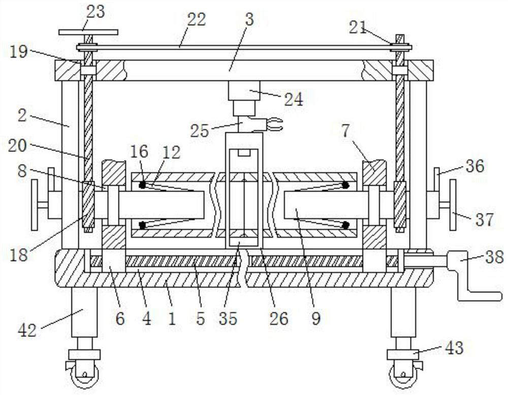
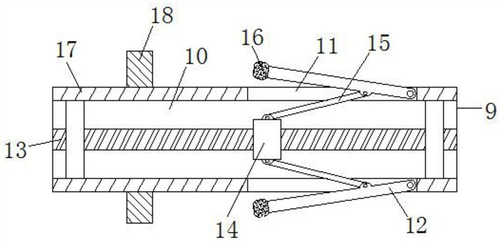
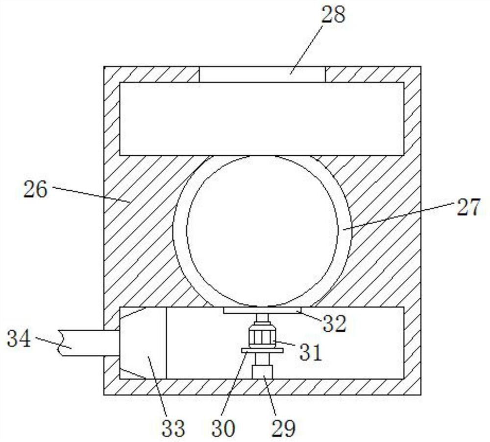
[0027] refer to Figure 1-6 , an industrial mechanical steel pipe positioning welding device, including a workbench 1, the four corners of the lower end of the workbench 1 are respectively fixedly connected with supporting legs 42, and the lower ends of the four supporting legs 42 are respectively fixedly connected with casters 43, and the casters 43 are self-locking. The steering wheel can be braked and locked when the device is working to ensure the working stability of the device. The supporting leg 42 includes a supporting rod 44 fixedly connected with the workbench 1. The inside of the supporting rod 44 is provided with a fourth empty slot 45, and the fourth empt...


PUM


Abstract

The invention relates to the technical field of mechanical equipment, in particular to an industrial mechanical steel pipe positioning and welding device. The device comprises a workbench, trundles are fixedly connected to the lower ends of four supporting legs correspondingly, a top plate is fixedly connected to the upper ends of four supporting columns, a first screw rod is rotatably connected to the interior of a first empty groove through a bearing, a threaded block is in threaded connection with the outer side of the first screw rod, a connecting plate is fixedly connected to the upper end of the threaded block, a first through groove is formed in the middle of the connecting plate, a positioning device is rotatably connected to the interior of the first through groove through a bearing, a welding gun is fixedly connected to the lower end of the first hydraulic rod, and a protective shell is fixedly connected to the middle of the upper end of the workbench. The industrial mechanical steel pipe positioning and welding device is reasonable in structural design, convenient to use, high in practicability and functionality, high in applicability, wide in application range, capableof guaranteeing the better welding effect, capable of protecting the working environment, more convenient to use and worthy of popularization.

Description

technical field [0001] The invention relates to the technical field of mechanical equipment, in particular to an industrial mechanical steel pipe positioning welding device. Background technique [0002] Steel pipe is a tool commonly used in existing industrial machinery. Steel pipe can not only be used to transport fluid and powdery solids, exchange heat, manufacture mechanical parts and containers, but also be used as building materials. Steel pipe is an economical steel , not only light in weight, can save steel, simplify construction, but also reduce the area coated with protective layer, saving investment and maintenance costs. [0003] The steel pipes generally need to be butt welded together before use, and the steel pipes need to be positioned butt welded together before welding, but the existing steel pipe welding device has the defect of troublesome positioning, and the steel pipe is unstable on the device during welding, and it is easy to shake , so that the weld...

Claims


Application Information

Patent Timeline
Patent Type & Authority Applications(China)
IPC IPC(8): B23K37/053B23K37/02B23K37/00B24B9/04B24B47/12B24B55/06
CPCB23K37/0531B23K37/0538B23K37/0252B23K37/00B24B9/04B24B47/12B24B55/06
Inventor 李高师
Owner 李高师
Learn More