A part clamping device for machining

A clamping device and mechanical processing technology, applied in the field of mechanical processing, can solve the problems of reducing work efficiency, increasing labor input, affecting the progress of mechanical processing, etc., and achieve the effects of improving firmness, increasing friction, and convenient and efficient adjustment

Active Publication Date: 2022-02-18
深圳市越宏五金塑胶技术有限公司
View PDF6 Cites 1 Cited by
  • Summary
  • Abstract
  • Description
  • Claims
  • Application Information

AI Technical Summary

Problems solved by technology

[0003] In the existing machining process, after the parts are clamped by the clamping device, when the height and angle are adjusted, the parts need to be loosened, repositioned, and then re-clamped to reduce work efficiency. Increase labor input and affect the overall machining progress

Method used


Image

  • A part clamping device for machining
  • A part clamping device for machining
  • A part clamping device for machining

Examples


Embodiment 1

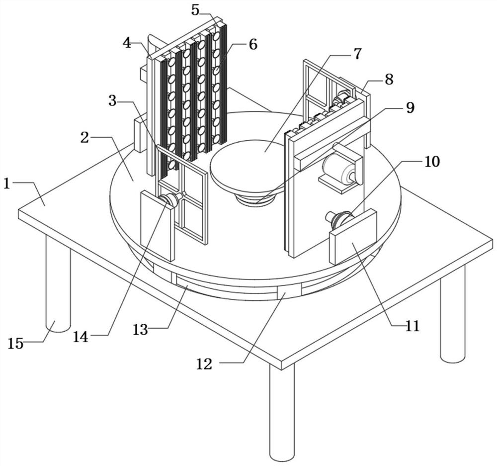
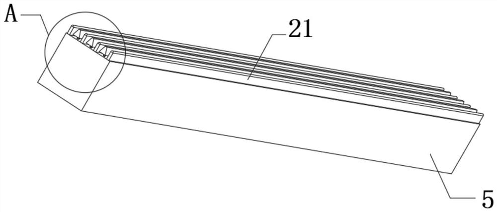
[0031] refer to Figure 1-5 , a component clamping device for mechanical processing, including a workbench 1 and a rotating plate 2, the top outer wall of the rotating plate 2 is fixedly connected with two fixed plates 11, and the outer walls of the opposite sides of the two fixed plates 11 are both The No. 1 hydraulic cylinder 10 is fixedly connected, and the outer walls on the opposite side of the two No. 1 hydraulic cylinders 10 are fixedly connected with the clamping plate 4, and the outer walls on the opposite side of the two clamping plates 4 are fixedly connected with the clamping rod 5 at an equal distance. And the outer wall of each clamping rod 5 is fixedly connected with extruding rods 21 at equal distances, and the outer wall of extruding rods 21 is fixedly connected with semicircular rods 22, and the outer walls of each clamping rod 5 are located at an equal distance between every two extruding rods 21. The No. 3 hydraulic cylinder 24 is fixedly connected, and the...

Embodiment 2

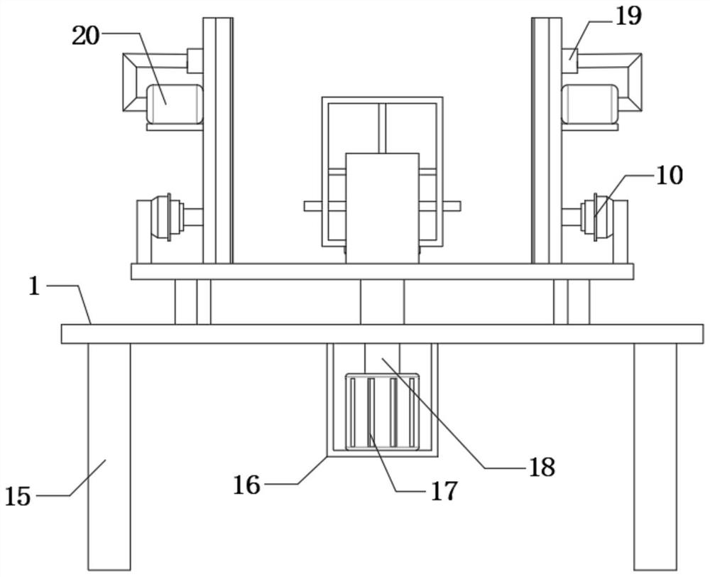
[0042] refer to Figure 6-7 , a component clamping device for mechanical processing, including a workbench 1 and a rotating plate 2, the top outer wall of the rotating plate 2 is fixedly connected with two fixed plates 11, and the outer walls of the opposite sides of the two fixed plates 11 are both The No. 1 hydraulic cylinder 10 is fixedly connected, and the outer walls on the opposite side of the two No. 1 hydraulic cylinders 10 are fixedly connected with the clamping plate 4, and the outer walls on the opposite side of the two clamping plates 4 are fixedly connected with the clamping rod 5 at an equal distance. And the outer wall of each clamping rod 5 is fixedly connected with extruding rods 21 at equal distances, and the outer wall of extruding rods 21 is fixedly connected with semicircular rods 22, and the outer walls of each clamping rod 5 are located at an equal distance between every two extruding rods 21. The No. 3 hydraulic cylinder 24 is fixedly connected, and the...


PUM


Abstract

The invention belongs to the technical field of mechanical processing, in particular to a component clamping device for mechanical processing. In the existing mechanical processing process, after the components are clamped by the clamping device, the height and angle When adjusting, it is necessary to loosen the parts, reposition them, and then re-clamp them, which reduces work efficiency, increases labor input, and affects the overall machining progress. The following solutions are proposed, including the workbench and the rotating plate. The present invention is provided with a motor, a rotating shaft, and a rotating plate. When the angle adjustment of parts needs to be adjusted, the motor is started, and the motor drives the rotating shaft to rotate, thereby driving the rotating plate to rotate. The inner wall of the ring chute slides to support and limit the rotation of the rotating plate, which ensures that the angle of the parts can be adjusted and at the same time improves the stability during the adjustment process.

Description

technical field [0001] The invention relates to the technical field of machining, in particular to a component clamping device for machining. Background technique [0002] Machining refers to the process of changing the shape or performance of a workpiece through a mechanical device. According to the difference in processing methods, it can be divided into cutting processing and pressure processing; the production process of the machine refers to the whole process of making products from raw materials (or semi-finished products). For machine production, it includes transportation and storage of raw materials, production preparation, blank manufacturing, processing and heat treatment of parts, product assembly, debugging, painting and packaging, etc. The content of the production process is very extensive. Modern enterprises use the principles and methods of system engineering to organize and guide production, and regard the production process as a production system with inp...

Claims


Application Information

Patent Timeline
Patent Type & Authority Patents(China)
IPC IPC(8): B25B11/00
CPCB25B11/00
Inventor 俞杭卫
Owner 深圳市越宏五金塑胶技术有限公司
Why Eureka
Try Eureka